Opticon OPR 2001, Specification Manual
The Opticon OPR 2001 is a cutting-edge handheld barcode scanner designed for seamless data collection. To unlock the full potential of this innovative device, make sure to download the comprehensive User Manual from our website for free. Discover step-by-step instructions and get the most out of your Opticon OPR 2001 experience.
Share
Download


Reviews:
No comments
Related manuals for OPR 2001
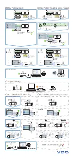
DLKpro
Brand: VDO Pages: 2

CR4400
Brand: Code Pages: 2

Quntek PN10
Brand: C Prox Pages: 7

BROCHURE
Brand: Symcode Pages: 56

MACE MM QR
Brand: Nedap Pages: 5

Conekt CSR-35L
Brand: Farpointe Data Pages: 2

ANPD050-02
Brand: Panasonic Pages: 12

ViVOpay VP3300 Series
Brand: IDTECH Pages: 20

VEB620
Brand: ViewSonic Pages: 73

Chipper 2X BT
Brand: Shopify Pages: 6

AVW200
Brand: Protel Pages: 10

DC9257L
Brand: RIOTEC Pages: 3

DC9250DP
Brand: RIOTEC Pages: 3

iLS6308KBU
Brand: RIOTEC Pages: 4

MaxiScan 3300
Brand: UBI Pages: 82

Omnia M700BK
Brand: Icarus Pages: 34

WPL304
Brand: Wasp Pages: 42

MMR2
Brand: Parabit Systems Pages: 22


