background image

Summary of Contents for SZ-III

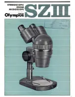
Page 1: ...STERlOSC01 C ZOOM MICROSCO ...

Page 2: ... utilization This may be called the definitive product of stereoscopic microscopes SPECIFICATIONS 1 Continuous flow of magnifications Zoom ratio 5 7 2 T o t a l Magnifications with objective 1x With eyepieces GlOx 7x 4 0 x With eyepieces G20x 14x 80 x 3 Inclined Binocular Head Inclination 45 Angle of Visual Axes 12 4 Range of Interpupillary Distance Adjustment With eyepieces GlOx at exit pupil 46 ...

Page 3: ...p Screw Pillar J Body Clamplng Screw I Stagm Clip Stage glass Plats r Strga dass Plat Clrmplng Screw STANDARD SET M i m p e Body Binocular Head I x Objective Stand Stage Pillar Eyepieces GlOx Stage Clips Large Stage Plates Clear and Smoked G l a s s Eyepiece caps Eye shades Cabinet Plastic Cover and Guarantee Card 1 set 1 set 1 pair 1 1 each ...

Page 4: ...wherein they are turned parallel to each other They further proceed through the morning vrriatibn system ZL1 and ZL2 and the fixed lens L1 reaching the Prism P1 where they again assume a 12 angle of visual axes and 45 inclination T h e n the beams enter porro prisms P2 and finally reach the eyepieces or Oculars Oc Continuous morning variation is performed by movement of the ZL lenses ...

Page 5: ...l W f i may be obtained by the following formula T d Mag Eyepie Mag x Objactive Mag x Magnification Indiitor Value Using Objective 1x Built in 20X 2 40X 5 0 2 5 50X 4 0 a 3 60x 3 3 8 3 5 70x 2 9 a 4 8 0 2 5 a Using Objective 0 5 x ...

Page 6: ...e focal length of the objective In case of the magnification change from a low number to a higher one the lower lens group 1st tens group rises to the middle and then comes down The upper lens group 2nd lens group is lo vered stright down The magnification ratio for the zooming system is 5 7 With the use of an objective 1x it varies from 0 75x to 3 x The following illustration indicates positions ...

Page 7: ...ilt in the microscope body and cannot be removed 0 75x and 1 5 x objectives are also availableas spbcsal acccwrim Sina the 1 x objective is already fixed i n the body other objectives if used must be attachad under the 1 x objective Objective Characteristics Focal Length 25 mm 12 5 m m I Magnification I Focal Length I Working Distance Field of View Diameter of the View Field of an Eyepiece 22 mm 1...

Page 8: ...ng thus enabling the user to freely choose whatever position he desires HEAD The head is designed with an inclinaton of 45 to the horizontal and a 12 angle of visual axn to allow the user to rnaintgin a comfortable posture and avoid fatigues during a prolongad abservation This also facilitates smooth coincidence of the two images right and left into one The range of interpupillary distance adjustm...

Page 9: ... be stabilized at a desired position by the pillar clamping screw ASSEMBLY AND OBSERVATION Pstts of the micmcmpe taka out of the cabinet will be assembled in the following d r Order of Assembly 1 Set the focusing part onto the body supporting block and secure it tightly by the providad scrcw 2 The coupling ring with the micmampc will be only slightly tightened and the body must be firmly affixed b...

Page 10: ...rum at 4 3 Focus the image by means of the focusing knob 4 Set the magnification drum at 0 7 5 If the image is out of focus perform focusing by adjusting the diopter ring s right or left or both as required DO NOT perform focus adjustment with the focusing knob 6 Once again set the magnification drum at 4 If the imagc is still out of focus adjust the diopter ring s right or left or both to bring t...

Page 11: ...e G20x paired 3 Epi illuminator LSG II with TF transformer 4 Illuminator LSD with TC transformer 5 Trans illuminating stand 6 Fluorescent illuminat ing stand LSF 7 Universal stand VS IV 8 Subsidiary pillar for conversion objective 0 5x I 9 Iris diaphragm i ...

Page 12: ......

Reviews: