


Encoder Installation Manual
EN 61326
NorthStar
™
brand
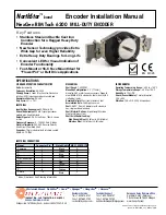
NexGen RIM Tach 6200
MILL-DUTY ENCODER
Key Features
• Stainless Steel and Ductile Cast iron
Construction for a Rugged Heavy Duty
Encoder
• New Sensor Technology provides Extra
Wide Gap for even Higher Reliability
• Extra Heavy Duty Bearings for Long Life
• Convenient LED for Visual indication of
Encoder Functionality
• Foot-Mount or 56-C Face Mount Ideal for
“Flower Pot” or Belt Drive Applications
SPECIFICATIONS
Worldwide Brands: NorthStar
TM
• Acuro
TM
• Dynapar
TM
• Hengstler
TM
• Harowe
TM
European Sales Representitive
Hengstler GmbH (Germany)
Uhlandstrasse 49, 78554 Aldingen
www.hengstler.com
INNOVATION - CUSTOMIZATION - DELIVERY
Customer Service:
Tel.: +1.800.873.8731
Fax: +1.847.662.4150
[email protected]
Technical Support
Tel.: +1.800.234.8731
Fax: +1.847.662.4150
[email protected]
WWW.DYNAPAR.COM
Headquarters: 1675 Delany Road • Gurnee,,IL 60031-1282 • USA
NorthStar™ brand is a trademark of DYNAPAR. All rights reserved.
Document No. 702952-0001, Rev.
C
©201
2
DYNAPAR
STANDARD OPERATING CHARACTERISTICS
Code:
Incremental
Pulses per Revolution:
60-2048
Phasing Sense:
A leads B for Counter-Clockwise
rotation (CCW) viewing encoder-mounted end
Quadrature Phasing:
90
°
±
45
°
Duty Cycle:
50%
±
15%
ELECTRICAL
Input Voltage Requirement:
5-26 Volts DC
Current Requirement:
95 mA typical per sensor
module plus line driver load
Output Signals:
5-26 V Line Driver, 150mA source
or sink
Frequency Response:
0 - 180kHz Data & Index
Electrical Immunity:
2kV ESD, Reverse Polarity,
Short Circuit, Powered Short
Connector:
10 pin industrial duty latching, sealed
NEMA 4 &12, IP65
MECHANICAL
Shaft Speed:
7,000 RPM
Mounting Configuration:
4.5” [115mm]
diameter, 56 C motor face or accessory flange to
meet NEMA MG1-4 standards; foot mount with 4
slotted bolt holes
Housing Material:
Cast Iron/Stainless Steel
Acceleration Rate:
3600 rpm/sec max
Shaft :
0.625” (16mm) diameter with standard
key, single or double ended
Shaft Material Options:
High Strength Carbon
Steel or Stainless steel
Shaft Axial/Radial Loading:
High Strength Steel:
50 lbf axial, 50 lbf radial
Stainless Steel:
35 lbf axial, 35 lbf radial
1
2
3
4
5
6
7
8
9
10
Black
Green
Blue
Violet
—
Red
Yellow
Gray
Orange
Braid
A
E
D
C
—
B
H
G
I
J
Signal
Connector Pin
Pigtail Cable
MS 3102E18-IT#
* Index (Z) optional. See Ordering Information
Common
B
A
Z *
No Connection
Vcc
—
B
—
A
—
Z *
Shield
ENVIRONMENTAL
Operating Temperature Range:
-40
°
C to +100
°
C
Storage Temperature Range:
-40
°
C to +120
°
C
Humidity:
to 100% RH
Shock (Sensor Module):
1 meter drop test,
30 G’s Min
Vibration:
18 G’s @ 5-2000 Hz spectrum
ELECTRICAL CONNECTIONS


