Nortel 8660 SDM, Installing
The Nortel 8660 SDM is a cutting-edge communication device perfect for businesses. Installing is simple with our free user manual available for download at manualshive.com. Get step-by-step instructions to maximize your device's capabilities and enhance productivity. Unlock the full potential of your Nortel 8660 SDM today.
Share
Download


Reviews:
No comments
Related manuals for 8660 SDM

G5000
Brand: CAME Pages: 32

MX10
Brand: ZIMO Pages: 38

ROVER
Brand: C3 Custom Coolers Pages: 16

Elemec3 013-02-0095-002
Brand: GAI-Tronics Pages: 12

WIM
Brand: Nedap Pages: 20

M3500N
Brand: K&K Pages: 10

DMX Analyzer
Brand: Blue Point Engineering Pages: 12

MVR911ECCN
Brand: Manfrotto Pages: 2

15-1995
Brand: Radio Shack Pages: 29

Xenta 102
Brand: TAC Pages: 76

J355HA M30-P1
Brand: FAAC Pages: 16
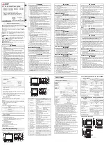
GT2512-STBA
Brand: Mitsubishi Pages: 2

KT-410C
Brand: KATO VISION Pages: 23

PR5200 Series
Brand: Powtran Pages: 36

RM2020
Brand: Tescom Pages: 15

Flamco FlexBalance EcoPlus C 1
Brand: Ke Kelit Pages: 5

1067/026
Brand: urmet domus Pages: 12

ESC Classic 50A
Brand: LETON Pages: 2


