background image


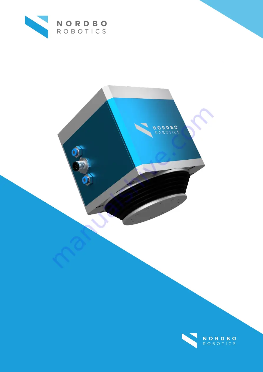
NAC-S20-15 Active Compensation Unit 

User Manual


Manual Version 1.0 

For Software Version 1.1 


Nordbo Robotics A/S 

[email protected] 


Noatunvej 2 

+45 81 81 98 81 

5000 Odense, Denmark 


Copyright © 2021, Nordbo Robotics A/S. All Rights Reserved.


Summary of Contents for NAC-S20-15

Page 1: ...ompensation Unit User Manual Manual Version 1 0 For Software Version 1 1 Nordbo Robotics A S info nordbo robotics com Noatunvej 2 45 81 81 98 81 5000 Odense Denmark Copyright 2021 Nordbo Robotics A S...

Page 2: ...e held responsible for the consequences that arise from misuse of or misunderstanding of any information stated in this document If any instructions are considered unclear it is the user s responsibil...

Page 3: ...iew of Web Interface 13 3 2 How to Access the Web Interface 14 4 Configuring the NAC Using Web Interface 18 4 1 Enable Disable Digital IO Interface Control 18 4 2 Configure Force Registers 19 4 3 Conf...

Page 4: ...ine Unit is Ready 34 7 3 Active Force Control 35 7 4 Initiate Calibration 35 7 5 Monitor NAC S20 15 Motion and Error 36 8 Control via Ethernet TCP IP Interface 37 9 Troubleshooting 41 9 1 Unable to Co...

Page 5: ...r unwanted situations can arise from not following the instructions correctly If safety instructions are not followed properly it may result in death personnel injury or equipment damage Before attemp...

Page 6: ...with where a constant specifiable force between tool and workpiece is required The NAC consist of two parts a tool unit and a controller The force can be specified through the controller using IO or e...

Page 7: ...AC S20 15 controllable by IO or ethernet NAC S20 15 Tool unit with a stroke of 20 mm and a maximum payload capacity of 15 kg Ethernet cable RJ45 Ethernet cable for connecting the NAC CTRL NAC Cable Co...

Page 8: ...0 1 MPa1 Nominal supply pressure 0 7 MPa Maximum flow rate 0 6 L min Electrical specifications Power supply voltage 24VDC 10 Power supply current consumption Typical 0 30A Up to 2A Digital IO interfac...

Page 9: ...AC S20 15 NAC CTRL Weight 2 6 Kg 1 2 Kg Dimensions Height Width Depth 121 141 mm 110 mm 110 mm 56 26 mm 106 13 mm 226 mm Mounting Tool Side Bolts Flange Diameter M5 10 60mm Mounting Fixation Site Bolt...

Page 10: ...e Used when mounting the tool unit on a stable surface or on a robot flange 2 Air in Connect tube to supply air to the tool unit 3 Interface for NAC control Unit Use the supplied cable to connect the...

Page 11: ...s ready for operation 2 LED status indicator Ethernet session indicator The LED is only turned On when there is a connection using the Ethernet TCP IP connection 3 LED status indicator System state in...

Page 12: ...ensation Unit User Manual Ver 1 0 NAC CTRL Interface Back Figure 8 ID Description Functionality C Power supply input Use to power the NAC controller D IO interface Use to connect and control the NAC u...

Page 13: ...ble by connecting the NAC CTRL to a PC via ethernet link Input the NAC CTRL s IP address in a web browser e g Internet Explorer or Google Chrome to access the settings The integrated web interface of...

Page 14: ...ed using the 4 bit IO register indexing o Is moving parameterization Timeout of is moving signal How long the actuator should stand still before it is considered not moving Distance threshold of how f...

Page 15: ...e controller using a Windows 10 PC Note Default settings for the NAC CTRL is having a static IP address of 192 168 1 100 Adding the device to a network with an existing device having the same IP addre...

Page 16: ...20 15 Active Compensation Unit User Manual Ver 1 0 Step 3 Click Change adapter options Figure 12 Step 4 Right click on Ethernet 3 and select Properties Note Ethernet number may vary from system to sys...

Page 17: ...16 of 44 NAC S20 15 Active Compensation Unit User Manual Ver 1 0 Step 5 Select Internet Protocol Version 4 TCP IPv4 and click Properties Figure 14...

Page 18: ...e Compensation Unit User Manual Ver 1 0 Step 6 Set the IP address to 192 168 1 42 Set the Subnet mask to 255 255 255 0 Figure 15 Step 7 Access the real time view using a browser by typing the IP addre...

Page 19: ...C Using Web Interface 4 1 Enable Disable Digital IO Interface Control Step 1 Click the checkbox Enable IO Interface Figure 17 Step 2 Navigate to the bottom of the configuration page and click Save Ste...

Page 20: ...the 4 force register selection digital input pins Figure 18 Step 1 Edit each row in the Force register table Assign your target force o Positive values correspond to a push force o Negative values co...

Page 21: ...eout timer and distance threshold to filter the signal Figure 19 Step 1 Set timeout value Note The Timeout corresponds to the time before the actuator starts moving the is moving signal is set to high...

Page 22: ...ring it off and on again to apply the new setting 4 4 Configuring Static IP Step 1 Navigate to the Network tab Figure 20 Step 2 Uncheck the box Enable DHCP so it is unset Step 3 Enter the desired stat...

Page 23: ...ep 6 Navigate to the bottom of the configuration page and click Save 4 5 Configure DHCP Client When the NAC CTRL is configured as a DHCP client it will obtain its IP address from a DHCP server on the...

Page 24: ...15 Updating the NAC CTRL Firmware Step 1 Contact your Nordbo Robotics contact for any updates Step 2 Download the update file and store it on your PC The file should have the file extension deb Step...

Page 25: ...s and corrupted firmware if the NAC S20 15 update process is interrupted Secure power supply against accidental deactivation Step 1 Contact your Nordbo Robotics contact for any updates Step 2 Download...

Page 26: ...ither using the Ethernet TCP IP protocol or the IO Interface The difference in possible controls is highlighted below TCP IP IO Setting target force and ramp time Configuring or calibrating load weigh...

Page 27: ...connect the NAC in a robotic application Figure 23 ID Unit Description 1 NAC S20 15 Nordbo Active Compensation unit 2 Air compressor Supplies air to the NAC for it to be functional 3 Robot controller...

Page 28: ...iption 1 NAC S20 15 Nordbo Active Compensation unit 2 Air compressor Supplies air to the NAC in order for it to function 3 NAC CTRL Controls the active compensation unit 4 Higher order controller PLC...

Page 29: ...tep 1 Connect from the air regulator to the NAC S20 15 with a 4mm air hose to the pneumatic push in fitting at the air intake on the NAC S20 15 Step 2 To keep a IP67 rating the exhaust on the NAC S20...

Page 30: ...ectors with caps Earth system parts prior to installation Use appropriate ESD equipment e g earthing straps Power Supply Using I O The NAC CTRL can be powered on by using I O by completing the followi...

Page 31: ...sert the female connector into the male connector on the NAC controller Power Supply Using External Power Supply The NAC CTRL can be powered by using an external power supply according to the diagram...

Page 32: ...screws Step 2 Insert the terminal plug with the wires in the IO of the PLC robot controller or other desired electrical switch Connectors Terminal block male Terminal block female Pin Function 1 GND...

Page 33: ...Prevent unauthorized access and inform operators of potential hazards 6 1 Idle In idle the tool unit is consuming no air and applying no active force control The passive force by the load is not comp...

Page 34: ...justing target force and ramp time 6 3 Retract Retract applies a high pull force to the NAC tool so the tool is retracted to its 0 position stroke length Any active force control is canceled and posit...

Page 35: ...5 is in motion Monitor if there are any errors 7 1 Logic Status of Input and Outputs When using NPN there is a difference between electrical high and low and the logical status 1 and 0 Logic state Ele...

Page 36: ...n these pins determines the force register index to be used e g 0101 will select force register index 5 Set pin 7 high to start active force control Figure 28 Active force control with switching force...

Page 37: ...an be used to monitor if the system NAC S20 15 is moving It will be logic high when the NAC S20 15 is standing still and logic low when NAC S20 15 is moving Pin 10 can be used to monitor if the system...

Page 38: ...DOUBLE 64 bit IEEE 754 Floating Point 8 10308 10308 Table 13 Overview of the Types supported by the Ethernet Interface The protocol defines a package format Each packet consists of two parts A header...

Page 39: ...request has been carried out successfully or the Boolean success indicator followed by the requested data and as such the size will be determined by the requested data Only one outstanding request can...

Page 40: ...f the NAC S20 15 0x15 TX Stream position UINT8 START 0x01 STOP 0x00 Indicates whether the system should stream the current position of the NAC S20 15 0x16 RX Position data DOUBLE Position m The curren...

Page 41: ...ad weight 0x29 TX RX Is moving UINT8 Moving 0x00 Not moving 0x01 Returns the is moving flag See Section Monitor NAC S20 15 Motion and Error page 36 0x30 TX RX Firmware version UINT8 4 UINT8 0 1 UINT8...

Page 42: ...ettings on your windows PC if they are set to a static IP address Static IP address Should be in the range 192 168 1 1 255 but different from 192 168 1 100 Subnet mask Should be set to 255 255 255 0 S...

Page 43: ...tory default parameters Parameter Default value DHCP client Off IP address 192 168 1 100 Subnet mask 255 255 255 0 Default gateway 192 168 1 1 Hostname nacserver Table 17 Factory default network setti...

Page 44: ...in 2 5 to 48V DC Digital input Scanning rate Galvanic isolation Pin 3 to 8 50 ms No Digital output Maximum current per output Overload protection Pin 9 10 220 mA No Ethernet interface Connection plug...

Page 45: ...Nordbo Robotics A S info nordbo robotics com Noatunvej 2 45 81 81 98 81 5000 Odense Denmark Copyright 2021 Nordbo Robotics A S All Rights Reserved...

Reviews: