Nilfisk-Advance SC350, Service Manual
The Black & Decker SC350 is a versatile slow cooker designed to simplify meal preparation. With its easy-to-use manual controls and user-friendly interface, this high-quality appliance ensures delicious, home-cooked meals every time. Download the free manual from our website to effortlessly master the art of slow cooking.
Share
Download


Reviews:
No comments
Related manuals for SC350

KX-FPG175
Brand: Panasonic Pages: 2
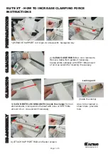
ELITE XT
Brand: Fastbind Pages: 3

Easy-Fax 90si
Brand: GateWay Fax Systems Pages: 13

2041
Brand: Janome Pages: 82

457 G 130
Brand: Singer Pages: 12

UnionSpecial 35800BLWG
Brand: JUKI Pages: 68

PowerBoss Armadillo 6X
Brand: HAKO Pages: 84

OFX 120
Brand: Olivetti Pages: 45

ALFA 650
Brand: IPC Soteco Pages: 40

KING COBRA 1200 PRO
Brand: U.S. Products Pages: 12

Minoltafax 1600e
Brand: Konica Minolta Pages: 127

SWL R1000 ET
Brand: Lavorwash Pages: 21

R100H
Brand: Minuteman Pages: 20

9082317010
Brand: Nilfisk-Advance Pages: 39

APW-896N/IP-420
Brand: JUKI Pages: 142

AMS-221F3020RSW/AW-3
Brand: JUKI Pages: 163

SF-S1403
Brand: Sunny Health & Fitness Pages: 10

OKIFAX 5400
Brand: Oki Pages: 116


