background image

1/01 revised 2/05   Form Number 56043058
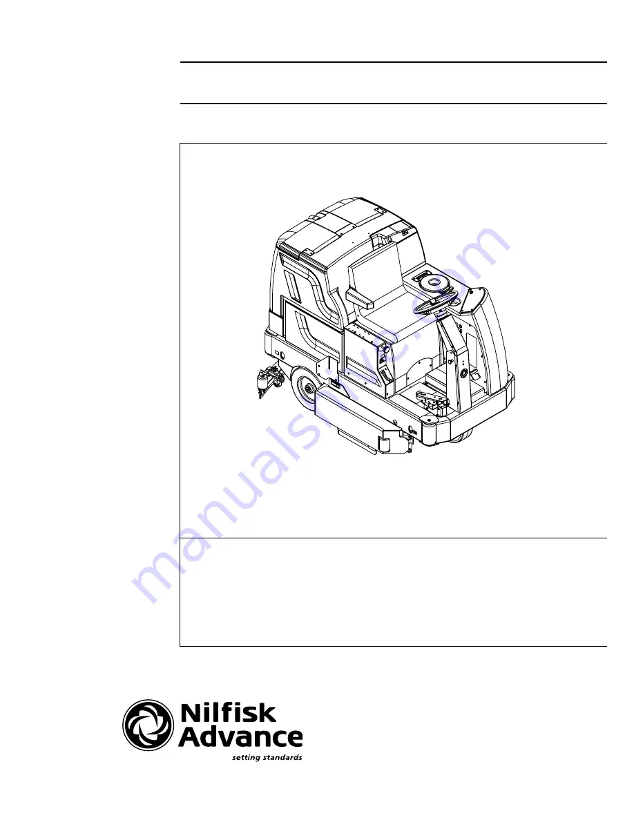
Hydro-Retriever

 3800

Hydro-Retriever

 2042

BR 1100, 1100C, 1100C-XL

SERVICE MANUAL

Advance MODELS 56410000 (disc), 56410350 (cyl.),

56410001 (2042), 56410500 (cyl. rollout),

56410501 (disc rollout), 56410502 (2042 rollout)

Nilfisk MODELS 56410002 (disc), 56410351 (cyl.),

56410425 (1100C-XL)

Summary of Contents for BR 1100

Page 1: ...iever 3800 Hydro Retriever 2042 BR 1100 1100C 1100C XL SERVICE MANUAL Advance MODELS 56410000 disc 56410350 cyl 56410001 2042 56410500 cyl rollout 56410501 disc rollout 56410502 2042 rollout Nilfisk MODELS 56410002 disc 56410351 cyl 56410425 1100C XL ...

Page 2: ... BRUSH SYSTEM MAINTENANCE 28 SCRUB BRUSH REMOVAL AND INSTALLATION C 29 SIDE SKIRT MAINTENANCE ADJUSTMENT C 29 SIDE BROOM SYSTEM 2042 BR 1100C XL 30 32 GENERAL FUNCTIONAL OVERVIEW 30 2042 BR 1100C XL SWEEP FRAME ASSEMBLY REMOVAL 31 SIDE BROOM ELECTRICAL BOX REMOVAL 31 SIDE BROOM LIFT MOTOR REMOVAL 31 SIDE BROOM MOTOR S REMOVAL 32 RECOVERY SYSTEM 33 35 FUNCTIONAL OVERVIEW 33 VACUUM RECOVERY SYSTEM S...

Page 3: ...OTING 56 57 INSTALLATION CHECKOUT FOR CONTROLLER 58 PROGRAMMER OPERATION 59 65 MAIN CONTROL BOARD FUNCTIONAL OVERVIEW 66 MAIN CONTROL BOARD TROUBLESHOOTING GUIDE 66 MAIN CONTROLLER ERROR CODES 66 69 MAIN CONTROLLER DIAGNOSTIC SERVICE TEST MODES 70 73 MAIN CONTROL BOARD SPECIAL PROGRAM OPTIONS 74 78 ELECTRICAL COMPONENT LOCATION 79 WIRING DIAGRAM SCHEMATIC 3800 BR 1100 80 81 WIRING DIAGRAM SCHEMATI...

Page 4: ...rts for the machine Use the space below to note the Model Number and Serial Number of your machine for future reference MODEL NUMBER SERIAL NUMBER OTHER MANUALS AVAILABLE FOR YOUR MACHINE The following manuals are available from the Nilfisk Advance Literature Service Department Hydro Retriever 3800 BR 1100 Hydro Retriever 2042 BR 1100C XL Parts List Form Number 56042410 Hydro Retriever 3800 BR 110...

Page 5: ...electrical components Never work under a machine without safety blocks or stands to support the machine Donotdispenseflammablecleaningagents operatethemachineonorneartheseagents oroperateinareaswhereflammable liquids exist Do not clean this machine with a pressure washer CAUTION This machine is not approved for use on public paths or roads This machine is not suitable for picking up hazardous dust...

Page 6: ... Ramp Climbing Ability gradeability Transport 15 83 grade Transport 15 83 grade Transport 12 99 grade 8 degrees Dry 8 degrees Dry 8 degrees Dry Sound Level 73 5 dBA at operator 73 5 dBA at operator 73 5 dBA at operator Transport Speed 4 6 mph 7 4 KPH 4 6 mph 7 4 KPH 4 6 mph 7 4 KPH Scrubbing Speed 3 5 mph 5 6 KPH 3 5 mph 5 6 KPH 3 5 mph 5 6 KPH Minimum Aisle Turn Width 86 inches 218 cm 86 inches 2...

Page 7: ...6043058 Hydro Retriever 3800 2042 BR 1100 5 SPECIFICATIONS 3800 BR1100FRONTVIEW 74 25 189cm 55 8 142cm SIDEVIEW 44 8 114cm 82 8 210cm 2042 BR1100C XLonly 51 130cm 47 5 121cm 2042 BR1100C XLFRONTVIEW revised 7 02 ...

Page 8: ... brake and disconnect the battery before servicing the machine BATTERIES AND CHARGERS Attention See the Electrical System manual section for battery installation and charger system requirements WHEEL DRIVE MOTOR GEARCASE OIL CHECK FILL The gearbox of the drive unit is originally filled with SAE 85 W oil in the amount of 300 cc 10 16 US fluid ounce It is recommended that the oil level be checked on...

Page 9: ...t Control Knob B D 12 Pre Sweep System Accessory If applicable A B D 13 Tilt Steering Mechanism and Seat Lever A B 14 Optional Accessories Headlight Safety Beacon Back Up Alarm Etc 15 Battery Charger auto turn ON OFF 16 Main Control Board Special Program Options Reference SVR Manual 56043058 and check all applicable program settings Examples stored error fault codes diagnostic SVR test mode scrub ...

Page 10: ...ng Skirts D W 50 Hopper Skirt D W 51 Hopper Dust Filter Gasket C D 52 Foot Pedal Switch Linkage A B D NOTE For additional service information see service manual form number 56043058 and operators manual form number 56041498 Defect Codes A needs adjustment C dirty or contaminated M missing B binding D damaged bent or torn W worn out L leaks WORK COMPLETED BY ACKNOWLEDGED BY Service Technician Signa...

Page 11: ...ive Pedal Directional Speed 9 Charger Plug 10 Drive and Steer Wheel 11 Circuit Breakers 12 Emergency Stop Switch Battery Disconnect 13 Scrub Brush Deck and Side Skirts 14 Rear Wheel 15 Battery Compartment 16 Recovery Tank Shutoff Float 17 Vacuum Motor Filter Housing 18 Squeegee Assembly 19 Squeegee Casters 20 Solution Filter 21 Recovery Tank Drain Hose 22 Tie Down Locations 4 45 Side Broom Wear Ad...

Page 12: ...on 30 Solution Button 31 Battery Condition Indicator 32 Hourmeter Status Display 33 Master On Off Key Switch 34 Scrub Mode Off Indicator 35 Normal Scrub Mode Indicator 36 Heavy Scrub Mode Indicator 37 Vacuum System Indicator 38 Vacuum System Fault Indicator 39 Presweep Dust Control Button 3800 BR 1100 only opt 40 Presweep Dust Control Indicator 3800 BR 1100 only opt 41 Presweep Power Indicator 380...

Page 13: ...verse the squeegee will go to the up position and the solution flow will be stopped Vacuum Button 29 This button is used to select the mode of operation for the vacuum squeegee system There are 3 modes of operation for this system These modes are OFF AUTO ON Following is a description of each mode and how they are selected OFF MODE In this mode the vacuum is off and the squeegee is in the up posit...

Page 14: ...s on This indicator will be OFF if the scrub mode is off or if the heavy scrub mode has been selected Heavy Scrub Mode Indicator 36 This indicator will be YELLOW if the heavy scrub mode has been selected but the scrub motor is off This will be the case if the throttle is in the neutral position The scrub motor will stay on for approximately 3 seconds after the throttle returns to the neutral posit...

Page 15: ...n if the key has been turned off The state of charge indication is reset to full charge when the batteries have been recharged It is also possible to choose between two different low voltage thresholds depending on whether maintenance free or standard batteries are being used have qualified service engineer perform this selection NOTE The following percentages are based on useable battery capacity...

Page 16: ...at and regulates the needed flow volume demand for the scrub brushes Located in the middle of the scrub deck is the electric solenoid valve L1 which stops and starts the solution flow to the scrub brushes See Figure 2 The electrical circuit that turns on energizes the solenoid coil is activated through the A4 control panel s switch buttons and the A3 main controller assembly Note See the Know Your...

Page 17: ...m fault in the main controller A3 Reference the Main Control Board Troubleshooting Guide in the Electrical System of this manual for further information SOLUTION SYSTEM MAINTENANCE Solution Tank See Figure 1 Weekly empty the solution tank remove the solution Drain Hose B from its storage area located underneath the left side brush skirt frame Direct the hose to a designated Disposal Site and flush...

Page 18: ...button to lower the scrub deck to the floor Note Don t turn the key switch off until disconnecting the battery pack push emergency disconnect knob 12 This procedure is done to prevent the scrub deck from automati cally raising when the key is turned off Turn Key OFF 3 Opentherightsidescrubbrushaccessdoorthenremovethe skirtassembly Locatesolenoid frontmiddleonscrubdeck and unplug the solenoid wire ...

Page 19: ... removal of the valve and bracket SOLUTION FILTER HOUSING REMOVAL 1 Drain the solution tank or put the flow control lever in the full OFF position to prevent solution loss 2 Open the right side scrub brush access door then remove the skirt assembly 2 knobs to access the solution filter 3 See Figure 5 Remove spin off the filter bowl for easier access to the inboard mounting clamps 4 Loosen the 2 Ho...

Page 20: ...gee lift The next step is the movement of the foot pedal for the needed A2 throttle output to the A1 speed controller which causes either FWD or REV motor action At the moment of A2 throttle input the A1 controller closes an internal coil driver and outputs a POS 36V signal from pin 8 wire color Brn Wht to the A3 J2 pin 6 connection This input signal causes the controller tooutputaNEG 36Vsignalfro...

Page 21: ...of this manual for specific fault descriptions and service repair actions RED RED YEL BLK RED BRN RED BRN ORN GRN ORN GRN GRN WHT GRN WHT GRN BLK YEL WHT YEL BLU M GRN WHT YEL BLU YEL WHT 1 9 16 8 B M B S2 S1 t BLK BLK ORN GRN RED BRN BLK BLK ORN GRN RED WHT GRN GRN BLK WHT BRN WHT WHT VIO BLK WHT GRN WHT BRN WHT BRN WHT BRN K3 R1 K3 S2 S1 D1 S3 A4 A3 F2 M Thermistor BRN WHT GRN WHT ORN BLK WHT BL...

Page 22: ...tainer Ring A from the lower actuator motor mount Pin B Next remove the pin from the deck mount bracket 5 Removethe 2 brushmotorwiresatthemotorterminals POS redwireontop andalsounplugthewireconnectortothewaterSolenoid Valve C 6 Remove the solution feed hose at the solenoid valve or solution filter housing 7 Remove the D Hex Nut from the outside rear Support Bar E and pull the ball joint stud end f...

Page 23: ... proper brush motor installation position is where the two cable mounting bolts wiring connections face the front and right side on the scrub deck platform FRONT R L SCRUB BRUSH GEARBOX REMOVAL DISC FIGURE 3 revised 10 01 Follow steps 1 10 of the Scrub Brush Deck Removal Disc section and steps 1 6 of the Scrub Brush Motor Removal Disc section 1 SeeFigure3 Removethehardwareitems R S that secure the...

Page 24: ...etely flush with the back end bracket of the motor install 3 Screws X with lock Washers Y through the gearbox mounting flange and into the pre drilled mounting holes in the back end bracket Important Make sure that the gearbox shaft is pointing in the correct direction before installing the mounting screws The gearbox shafts should both be pointing left if viewing the motor from the back end and t...

Page 25: ...UB BRUSH SYSTEM AA X Motor terminals must be on the right hand side of the machine pointing towards the front of the machine FRONT U W X Y Leads at 12 00 V Shafts facing LEFT Z Apply Never Seize VIEW X Y Commutator End Back End FIGURE 4 FIGURE 5 revised 12 02 ...

Page 26: ... are to be raised or lowered to compensate for blade wear 2 To adjust remove the Skirt Assemblies AC from the Scrub Deck AE to access the Adjuster Collars AD Adjustment Tip The skirts Retainer Knobs AB can be loosened with skirts left on and the Adjuster Collars AD rotated by reaching under the skirt housing 3 Turn the Adjuster Collars AD Up or Down to where the blades just fold over enough when s...

Page 27: ...mount of tape around the spring housing to prevent it from spinning out of adjustment Service Tip Shown in the Electrical System is the actuator power cord adapter PN 56407502 and instructions for use This tool can be used to help position raise or lower the drive nut housing for ease in the actuator mounting pin installations An additional method to control the output to the pad brush lift actuat...

Page 28: ...onnect the brush lift motor wire harness at the motor 6 Remove the mounting hardware Screw G and Nut H then separate the Support Arm I from the machine s out board frame mounting bracket right side of machine 7 On both sides of the machine remove the 4 item J Hex Nuts from the front Ball Joint Ends K and then separate the deck support arms from the machine frame Note To access the top Hex Nuts J p...

Page 29: ...roximately 2 1 2 inches 64 mm To adjust loosen the Lock Nuts M on the 4 Connecting Rods L and turn the center section of the rod s to raise or lower lengthen or shorten the levelness of the brush deck Note The assembly length on the ball joint connecting rods are adjusted to 5 inches 127 mm from ball joint to ball joint as shown in Figure 9 3 Re tighten the connecting rod lock nuts and lower the b...

Page 30: ... right or left side and remove the belt guard s O 4 screws each 2 Important Service Tip The left and right side drive belts are not the same lengths they must be ordered individually P N 56410217 left side P N 56410215 right side 3 Loosen the scrub brush belt tension hardware on the Belt Idler Pulley P using a 5 8 wrench Pull the idler wheel away from the backside of the belt and roll the belt off...

Page 31: ...erator will notice a small amount of water leaking out underneath the side skirts The skirt height adjustment is automatic on this system using spring tension and movable linkage arms to control the blade pressure The side skirt assemblies must move up and down freely for proper operation To replace the scrub system side skirts See Figure 10 Remove the 2 Hairpins N and swing the skirt assemblies o...

Page 32: ...two main cylindrical scrub brushes and collected in a removable debris tray Thesidebroommotorassembliesareraisedandloweredbyahorizontallymountedelectricactuatormotor Theactuatorlinkageconnectsdirectly to 2 wire cables that controls the broom assemblies vertical travel The operator pressing the On Off Sweep Control Button 43 located on the control panel A4 activates the operation of the side brooms...

Page 33: ...rds the right broom just enough to clear the mount bracket Then pull the box down to remove Note The box is fitted with pieces of gasket sealing material that makes the box fit very snug tight SIDE BROOM LIFT MOTOR REMOVAL 1 LowersidebroomstothefloorthenpushtheBatteryDisconnectKnob 12 intoopenbatterycircuit AlsomovethebroomheightAdjustment Lever H to the full down position 2 See Figure 1 Remove th...

Page 34: ...hrough the bumper opening use a 3 4 wrench 3 4 socket ratchet to remove the Nut O Spring P that holds the gear motor Mount Bracket Q 4 To remove the complete broom motor assembly step on the Broom Housing R to compress the bristles then pull it out from under frame 5 Remove the 3 broom mount Screws S and remove the Broom T 6 Next loosen the Set Screw U and remove the Brush Drive Hub Screw V Then p...

Page 35: ...lows down because of the increased volume large size of tank With the decreased air speed the heavier water falls to the bottom of the recovery tank Then at the same time the airflow continues through the tank shutoff float vacuum motor and is exhausted out of the vacuum exhaust hose No wastewater ever actually moves through the vacuum motor just working air The vacuum system uses a shutoff float ...

Page 36: ...it out in warm water Note The filter must be completely dry before reinstalling To inspect the vacuum shut off float just open the left rear recovery tank cover to access the float cage assembly front left in recovery tank The cage openings must be kept free of any debris that can restrict maximum airflow To keep it clean wipe off with a rag regularly or remove and flush with water The cage is a t...

Page 37: ...FORM NO 56043058 Hydro Retriever 3800 2042 BR 1100 35 RECOVERY SYSTEM C FRONT M L J K H D I F E G A B To Squeegee FIGURE 2 revised 12 02 ...

Page 38: ...J3 Thisraisesthesqueegee off the floor to the back up position which is half of the normal distance observed when in the machine scrub off mode Moving the drive pedal back to the neutral forward position opens the A2 throttle reverse output and the A3 control board loses its input voltage signal The J3 connector output reverses the polarity and lowers the tool back onto the floor SQUEEGEE LIFT ACT...

Page 39: ...FORM NO 56043058 Hydro Retriever 3800 2042 BR 1100 37 SQUEEGEE SYSTEM FRONT F E D C H G B N L A FIGURE 2 revised 12 02 ...

Page 40: ...ments height and angle The recommended adjustment steps are to set the tool angle first then adjust the blade height Adjusting the Squeegee Angle Adjust the squeegee angle whenever a blade is reversed or replaced or if the squeegee is not wiping the floor dry 1 Park the machine on a flat even surface and lower the squeegee Then drive the machine forward enough to have the squeegee blades fold over...

Page 41: ...FORM NO 56043058 Hydro Retriever 3800 2042 BR 1100 39 SQUEEGEE SYSTEM I J K J K M M Q Q R R O P FRONT N L FIGURE 3 FIGURE 4 revised 12 02 ...

Page 42: ...s to the two separate motor circuits armature field per the percentage of the A2 throttle movement MOTOR OPERATION Themotorhas 4 terminalconnections 2 armatureA1 A2and 2 fieldD1 D2 Themotorarmaturecircuitreceivesfromthecontrollerachopped ontimeofftime PWMvoltageandcurrentoutputthatvariesthemotorspeed Thefieldcircuitseesthecurrentdirectionpolaritychangethateffects the rotation of the motor CW for F...

Page 43: ...WHT GRN D2 D1 B M B S2 S1 BLU RED GRN WHT BLK RED ORN GRN RED BRN RED BRN BLK BLK ORN GRN RED WHT GRN GRN BLK BLK BRN WHT WHT GRN K3 S2 S1 S3 A4 A3 F2 BRN WHT GRN WHT GRN WHT ORN BLK WHT BLK WHT GRN GRN BLK BRN BLK WHT WHT WHT BRN BLK GRN GRN BRN RED WHT 8 J2 14 7 1 J5 J4 7 1 12 6 J1 1 2 4 3 7 1 12 6 A2 A1 GRN BRN WHT GRA K1 To M2 or M2 M11 A1 FRONT A3 K1 M6 A2 S2 S3 S1 FIGURE 1 revised 12 02 ...

Page 44: ... logic circuits WHEEL DRIVE TROUBLESHOOTING GUIDE Problem Possible Cause Wheel drive motor will not run in forward and reverse Batteries need charging low battery voltage recharge batteries Wheel Drive Motor Circuit Breaker F3 tripped reset circuit breaker Control Circuit Circuit Breaker F2 tripped reset circuit breaker Parking Brake 6 set release parking brake Emergency Stop Switch 12 tripped pul...

Page 45: ...EERING CHAIN REMOVAL 1 See Figure 2 Loosen the bolt and lock nut on the Chain Tension Sprocket B to release the steering chain tension 2 Remove both master links securing the steering chain at the Steering Plate C then remove the chain 3 Re assemble in reverse order refer to steering chain adjustment section for proper chain routing and tension adjustment Steering System Maintenance Oil the chain ...

Page 46: ... Be careful not to damage the threads and bearing surfaces when dropping the spindle down through the frame in removing it from the chassis 7 Inspect bearings and seal and replace as needed Remove the 4 H Screws to separate the spindle weldment from the steer plate and drive wheel motor mount 8 To make further service repairs see the drive wheel motor and gear housing removal steps in this manual ...

Page 47: ...FORM NO 56043058 Hydro Retriever 3800 2042 BR 1100 45 WHEEL DRIVE SYSTEM FRONT H B D E F G Spindle Weldment Steer Plate Drive Wheel Motor Mount FIGURE 4 revised 12 02 ...

Page 48: ...flange and motor field housing to reference when re assembling 5 Tap the motor Mount Flange L motor end bell completely off from the motor Field Housing P Note Use a piece of hardwood or brass when tapping on the motor flange to remove 6 See the carbon brush inspection instruction in this manual section for the steps to follow when removing the motor brush end bell assembly 7 Inspect test and make...

Page 49: ...SYSTEM FRONT I J K L M N R S U V O Q P T W Note position of fill hole to check oil level and fill FIGURE 6 TORQUE SPECIFICATIONS Screw Size Qty Torque I M10x 35 8 59 Ft lb 80Nm K M8x30 8 29 5 Ft lb 40Nm O M10x30 8 59 Ft lb 80Nm R M5x20 13 7 4 Ft lb 10Nm revised 12 02 ...

Page 50: ...ler W as shown in Figure 6 If this separation occurs it will be necessary to remove the gear housing and reconnect the drive coupler THROTTLE CONTROL NEUTRAL ADJUSTMENT If the drive pedal or electronic throttle have been removed or replaced the neutral position for the pedal will have to be set Follow the steps below to accomplish this 1 Turn the Master On Off Key Switch 33 to the OFF position set...

Page 51: ...y stand 3 Remove the hub retainer Bolt A and rear wheel to inspect and service brake shoes REMOVAL OF BRAKE ASSEMBLY Service Tip To gain more service access on the back side of the brake assembly remove the scrub brushes lower scrub deck and disconnect the battery pack by pushing in the emergency disconnect knob 12 1 Follow steps 1 3 in the Brake Shoe Assembly Inspection section 2 Remove the Hex S...

Page 52: ...r clockwise 3 See Figure 2B Hold the brake input shaft firm and at the same time install the brake arm to the splined shaft also having the backside of the arm contacting its frame stop as shown Note These assembly steps are important so both left and right arm angles are adjusted to provide equal shoe to drum contact To achieve proper wheel brake engagement and pedal travel 4 Next install the bra...

Page 53: ...ing 4 Retighten lock nut and secure pin retainer clamp BRAKE CABLE REMOVAL 1 Remove battery box by following step one in Brake Cable Adjustment section 2 See Figure 3 First loosen the rear cable adjustment Lock Nut K then unsnap the clevis pin retainer clamp and push the pin out of its mounting bracket 3 Unthread the clevis assembly from cable end and salvage it will be reused 4 Use a screwdriver ...

Page 54: ... Advance or by a qualified electrician 1 Removethebatteriesfromtheirshippingcrateandcarefullyinspectthemforcracksorotherdamage Ifdamageisevident contactthecarrier that delivered them or the battery manufacturer to file a damage claim 2 Turn the Master Key Switch 33 OFF O and remove the key Tip back the recovery tank to expose the battery compartment 3 SeeFigure1 Using 2 peopleandanappropriatelifti...

Page 55: ...cing the batteries BATTERY MAINTENANCE Proper maintenance of electric vehicle batteries can greatly extend their life Well maintained batteries may last up to 3 years but failure after 1 year is common if maintenance has been poor There are 3 simple rules for good battery maintenance Maintain Proper Electrolyte Level Weekly Use distilled water in batteries whenever possible If batteries are discha...

Page 56: ... the motor rotation in setting the correct drive nut dimension Instructions for Squeegee and Side Broom Lift Actuator Drive Nut Adjustment 4 See Figure 3 Hold onto the Actuator Drive Nut A and press the rocker switch to run the drive motor and retract the nut towards the motor housing its IN limit 5 Measure the position of the drive nut on the actuator shaft Manually turn the plastic drive nut to ...

Page 57: ...asticdrivenut as shown with the nut pin pocket away from the motor 2 Follow steps 4 10 in the section labeled Instructions for Squeegee and Side Broom Lift Actuator Drive Nut Adjustment refer ence previous page 3 After adjusting the actuator drive nut di mensions follow steps 10 and 11 in the Scrub Brush Lift Actuator Removal manual section to reassemble Service Tip See Figure 5 Note the correct o...

Page 58: ...rmation In this example the display shows No Faults Present indicating that the controller has not detected anything out of the norm 3 Put the programmer in test mode and observe the status of inputs and outputs in the forward direction In this example the display shows that the forward input did not activate when forward was selected which means the problem is either in the electronic throttle or...

Page 59: ...ain contactor coil shorted field winding shorted 2 Field winding shorted 3 2 OOO OO Main contactor welded 1 Main contactor stuck closed 2 Main contactor driver shorted 3 3 OOO OOO Motor field winding open 1 Field winding connection open 2 Field winding open 3 4 OOO OOOO Missing contactor 1 Main contactor coil open 2 Main contactor missing 3 Wire to main contactor open 4 1 OOOO O Low battery voltag...

Page 60: ...d the programmer will display a diagnostic message If youareconductingthecheckoutwithoutaprogrammer lookuptheLEDdiagnosticcodeintheDIAGNOSTICSsectionofthischapter Table 1 When the problem has been corrected it may be necessary to cycle the key or seat switch to clear the fault code 4 While sitting on the seat operate the throttle The motor should begin to turn in the selected direction If it does ...

Page 61: ...is step has been completed the programmer displays the controller s model number date of manufacture and software revision code Following this initial display the programmer displays a prompt for further instructions FIGURE 7 The LED in the corner of the key lights up to identify the mode of operation Scroll the 4 line display up or down with these 2 keys A 4 line LCD display is presented in this ...

Page 62: ...s of a menu are displayed at a time The item at the top of the display window is the selected item To select an item scroll within the menu until the desired item is positioned at the top of the display window The selected item is always the top line In the Program mode the selected item is highlighted by a flashing arrow To modify a parameter or obtain more information about it it must be scrolle...

Page 63: ...ed together with the PROGRAM and DIAGNOSTICS keys and 3 to initiate certain commands such as the Self Test More information is available in all of the programmer operating modes After using the MORE INFO key to display additional information about the selected item press the MORE INFO key again to return to the original list OPERATING MODES PROGRAM MODE In the Program mode accessed by pressing the...

Page 64: ...opitemonthelist itonlyneedstobeamongthefouritemsvisibleinthewindow The Test mode is useful for checking out the operation of the controller during initial installation and also for troubleshooting should problems occur The MORE INFO key when used in the Test mode causes additional information to be displayed about the selected item top line in the window TEST MENU THROTTLE Throttle reading as of f...

Page 65: ...NU ANTI TIEDOWN Mode Select 1 switch closed at startup CONT COIL FLD SHORT Contactor driver overcurrent or field winding short CURRENT SHUNT FAULT Current sensor error EMR REV WIRING Emerg reverse wiring check failed FIELD OPEN Motor field winding open HPD High pedal disable HPD activated HW FAILSAFE Hardware failsafe activated LOW BATTERY VOLTAGE Battery voltage too low M SHORTED M shorted to B M...

Page 66: ...ey will light just as when the programmer is in Program mode To distinguish between the program and Special Program modes look at the menu items in the display TheMOREINFOkeyisusedinitiallytoaccesstheSpecialProgrammode andonceyouarewithintheSpecialProgrammode itisusedtoperform the desired tasks To adjust the contrast in the display window for example select Contrast Adjustment by scrolling until t...

Page 67: ...or field winding open HPD High pedal disable HPD activated HW FAILSAFE Hardware failsafe activated LOW BATTERY VOLTAGE Battery voltage too low M SHORTED M shorted to B MAIN CONT WELDED Welded main contactor MISSING CONTACTOR Missing contactor NO KNOWN FAULTS No known faults OVERVOLTAGE Battery voltage too high SRO Static return to off SRO activated THERMAL CUTBACK Cutback due to over under temp TH...

Page 68: ...n one error exists the display will sequence through the error codes at one second intervals The error display will show on the hour meter as the letters Err followed by a two digit code EX Err01 would be a non fatal control fault When troubleshooting any Fault Description noted with a double asterisk followtheinstructionsfortemporarilydisablingthecontrolboardsspecialfaultdetectionprogram SeetheMa...

Page 69: ...high circuit open resistance infinity Repair or replace 3 Controller failure replace Err17 Scrub motor cable thermistor fault Machine exposed to a very cold or hot operating temperature Allow machine to be warmed or cooled to room temperature Temp range 32ºF to 185ºF 0 to 85ºC 2 Cable failure replace the brush motor negative cable assemble this is a special cable and must be replaced with an origi...

Page 70: ...tions down line Repair 2 Possible controller failure Err40 Wheel drive auxiliary direction input fault 1 Check Aux driver Brn Wht wire for continuity If open repair wire 2 Check for a 36V auxiliary drive output if it reads 0 volts replace A1 Curtis controller if it reads 36V replace A3 main controller Err41 Pre sweep dust control contactor coils Check coil resistance PN 56410087 spec 216 Ohms or K...

Page 71: ... and sees additional two digit number s as shown in error code range in the chart below A complete check of that fault area would be completed before installing a new main control board Re check troubleshooting actions Error Code Fault Area By Machine System for Main Controller Error Codes 60 A 61 Vacuum Motor Solenoid Err24 Err31 89 62 B 63 Brush Motor Solenoid Err07 Err17 96 C 74 Squeegee Actuat...

Page 72: ...tion of each switch and indicator is described in the following pages 7 To exit this mode turn the master on off key switch to the off position CONTROL PANEL 23 Main Power Indicator 24 Solution System Fault Indicator 25 Scrub Off Button 26 Normal Scrub Button 27 Heavy Scrub Button 28 Solution System Indicator 29 Vacuum Button 30 Solution Button 31 Battery Condition Indicator 32 Hourmeter Status Di...

Page 73: ...ctuator outputs The digit second from the left will be P if the pre sweep foot pedal switch is closed or if side broom unit is installed If over current faults are present the status display will indicate the fault codes Output Controls The control panel switches are used to control various output functions of the main control unit Below is a list of each switch and the function it controls Follow...

Page 74: ...sed actuator at limit open circuit or open output driver The horn switch has no effect in this state Heavy Scrub Switch 27 This switch is used to control the output to the squeegee lift actuator Pressing and releasing this switch will cycle the actuator output through 4 states These are 1 output off direction up 2 output on direction down 3 output off direction down 4 output on direction up When t...

Page 75: ...Service Test Mode you are at step one Press this switch and observe step 2 The order of output activation is as follows 1 pre sweep off dust control off 2 pre sweep on dust control off 3 pre sweep off dust control off 4 pre sweep off dust control on 5 pre sweep off dust control off 6 pre sweep on dust control on The pre sweep and dust control indicators 40 41 provide the following status informati...

Page 76: ... the normal scrub mode is 4 Pressing the heavy scrub button will enable the scrub system and set the scrub pressure to the last selected value for the heavy scrub mode The status display will momentarily display the scrub pressure setting This is indicated by PA followed by a number Subsequentpressesoftheheavyscrubbuttonwillstepthepadpressuresettingthroughtheallowablerangeuptothemaximumvalueprogra...

Page 77: ... pressure level 9 The display will now show done indicating that the normal scrub mode is programmed 10 Turn the master key switch off To program the heavy scrub mode for fixed scrub pressure perform the following steps 1 Turn the master key switch off 2 Press and hold the heavy scrub button 3 Turn the master key switch on while continuing to hold the heavy scrub button until the status display sh...

Page 78: ...ll now select between the two options For standard wet cell batteries select Std and for maintenance free batteries select FrEE 7 To save the new setting turn the master on off key switch to the off position 8 The new setting will be saved and will remain in effect until it is changed again Recall Of Stored Error Fault Codes Whenever an electrical system fault is detected by the main control unit ...

Page 79: ...ition 2 Press and hold the scrub off switch and the vacuum switch 3 While holding both switches turn the master on off key switch to the on position 4 Continue to hold both switches until the hourmeter status display shows 1 or 2 and the vacuum yellow indicator is lit 5 Release both switches 6 Pressing and releasing the vacuum switch will now select between 1 or 2 Use 1 for a single vacuum motor a...

Page 80: ...uilt with dual side brooms standard FACTORY DEFAULT SB The disc type scrub machines models 3800 BR1100 are designed to be equipped with the pre sweep dust control option PS The cylindrical models 3800C BR1100C are designed to be equipped with the side broom option SB To operate either sweeper accessory attachment the needed sweep option PS or SB program must be activated This program option can be...

Page 81: ...splay Control 5 Fuse 250 Amp 6 Circuit Breaker 10 Amp 7 Circuit Breaker 80 Amp 8 Horn 9 Contactor Main 10 Contactor Vac Motor 11 Contactor Brush Motor 12 Solenoid Valve 13 Actuator Motor Brush Lift 14 Actuator Motor Squeegee Lift 15 Scrub Brush Motor Disc 16 Vacuum Motor 17 Wheel Drive Motor 18 Switch Main Key 19 Switch Charger Interlock 20 Switch Seat 21 Diode Assembly 22 Scrub Brush Motors Cylin...

Page 82: ...embly X2 Charger Connector Charger Plug Assembly revised 2 05 M M FUSE 2 AMP F7 RED RED YEL BLK RED BRN RED BRN ORN GRN ORN GRN GRN WHT GRN WHT GRN BLK BLK ORN WHT YEL BRN YEL WHT YEL BLU M M GRN BRN YEL GRN GRN WHT YEL GRN GRN BRN YEL BLU YEL WHT A2 1 9 16 8 BLK BLK BLK BLK RED RED RED RED BRN YEL BRN YEL BRN YEL BLU BLK BLU YEL BRN YEL WHT BRN K1 K4 K5 S4 F4 M7 Optional M9 Optional K6 S7 S8 K6 F...

Page 83: ...LK 20A B ORN VIO 37A B WHT BLU 96A B GRN BLK 50A B BLK OI B 1 7 WHT ORN 93A B YEL BRN 41A B ORN WHT 39A B WHT BRN 91D A WHT BRN 91I A WHT BRN 91E A BLK OL A BLK OM A BLK OU A BLK OU B WHT BRN 91I B BLK OA B BLK ON A VIO 7A A VIO 7A B ORN GRN 35C A BLK OO A BLK OY A ORN 3A B BLK OG B YEL 4A B WHT BRN 91H A WHT BRN 91H B WHT BRN 91E B WHT BRN 91F B WHT WIRE 5 WHT WIRE 6 WIRE 3 BRN YEL 14A A VAC MOTO...

Page 84: ...CRUB SIDE BROOM SCRUB OFF 2 7 HORN 3 8 4 7 6 1 12 DISPLAY PANEL SWITCH CONNECTIONS MEMBRANE SWITCH DETAIL A M 1 9 16 8 B B M S1 S2 M M M M M M M BRN 6 1 A3 X1 YEL GRN 7 ORN GRN 8 GRA RED WHT F3 ORN GRN BLK WHT WHT J3 BLU BLK L1 ORN WHT 6 J2 2 YEL YEL BLU F2 GRN BRN VIO BLK GRN X1 14 RED BRN YEL BLU GRN BRN J4 GRA RED RED BRN 7 12 BLK M1 GRN 5 BLK WHT 3 BLK BLK GRN 3 YEL BRN GRN D1 BRN YEL BLK ORN ...

Page 85: ...A B ORN VIO 37A B WHT BLU 96A B GRN BLK 50A B BLK OI B 1 7 WHT ORN 93A B YEL BRN 41A B ORN WHT 39A B WHT BRN 91D A WHT BRN 91I A WHT BRN 91E A BLK OL A BLK OM A BLK OU A BLK OU B WHT BRN 91I B BLK OA B BLK ON A VIO 7A A VIO 7A B ORN GRN 35C A YEL 4A B WHT BRN 91H A WHT BRN 91H B WHT BRN 91E B WHT BRN 91F B BLU 6A B YEL 4A B VIO 7A B GRN 5A B YEL 4B B YEL 4A A YEL 4B B BRN 1C A GRA 8A B BLK OB B BR...

Page 86: ...Advance A E Tel 30 8 Thoukididou Str 210 963 3443 Argioupoli Fax 30 Gr 164 52 Athens 210 965 0975 Greece Holland Sales Sub Nilfisk Advance B V Phone 31 Camerastraat 9 2e verdieping 36 546 07 00 1322 BB Almere Fax 31 Postbus 60112 36 523 51 48 1320 AC Almere www nilfisk advance nl Ireland Sales Sub Nilfisk Advance Limited Phone 35 28 Sandyford Office Park 3 12 94 38 38 Sandyford Dublin 18 Fax 35 Ir...

Page 87: ...42 Fuitian Free Trade Zone Fax 86 755 518038 Shenzhen 8359 1063 P R China China Suzhou Nilfisk Advance Professional Phone 86 512 Cleaning Equipment Suzhou Co Ltd 8918 5656 306 Su Hong Zhong Road Build 2 Fax 86 512 Suzhou Industrial Park 8918 5666 215021 Suzhou P R China Hong Kong Sales Sub Nilfisk Advance Ltd Phone 852 2001 HK Worsted Mills Ind l Bldg 2427 5951 31 39 Wo Tong Tsui St Fax 852 Kwai C...

Page 88: ...www nilfisk advance com 2005 Printed in USA ...

Page 89: ...Loc Bolt Refer to Figure 2 when ordering replacement parts INSTALLATION INSTRUCTIONS WARNING PERSONEL INJURY AND MACHINE DAMAGE MAY RESULT IF THE FOLLOWING INSTRUCTIONS ARE NOT READ AND UNDERSTOOD FIGURE 1 1 Inspect the sling Do not use if any damage from cracking wearing or fraying is visible 2 Disconnect power supply batteries 3 Drain both the solution and recovery tanks 4 Remove both presweep a...

Page 90: ... Use a crane or hoist rated for at least 3 000 lbs 1 350 kg when lifting The lift sling has a maximum capacity of 2 800 lbs 1 270 kg 6 Make sure that no one is present on or below the machine while lifting 7 Lift swing and lower slowly FIGURE 2 ...

Page 91: ...d remove the Front Panel B 3 Remove the 2 C Button Plugs from the Front Panel B 4 Install the Grommet 5 into the bottom hole as shown 5 Insert the wires from the Headlight 1 through the Grommet 5 and then secure the Headlight to the Front Panel B as shown using the Screw 3 and Nut 4 from the kit Snap the Headlight Guard 2 over the Headlight 1 as shown 6 Connect the 2 Terminal Tabs 6 to the Headlig...

Page 92: ...Wire assembly 4 as shown 3 Attach the RED wire from WireAssembly 4 to the terminal and the BLACK wire from Wire Assembly 4 to the termi nal of the Back Up Alarm 2 then slide the Terminal Insulators 3 over each ter minal 4 Under the left rear corner of the machine there are 2 pre drilled holes A Mount the Back UpAlarm 2 with the 2 Screws 1 from the kit as shown 5 Route the Wire Assembly 4 up throug...

Page 93: ...ment parts INSTALLATION INSTRUCTIONS WARNING DISCONNECT BATTERIES BEFORE SERVICING FIGURE 1 FRONT D E B C A 1 See Figure 1 Remove the 6 A Screws and remove Panel B from the machine Remove and discard the 2 C Plugs 2 Install the 2 D Circuit Breakers and the 2 E Reset Boots as shown 3 The wiring for these two circuit breakers is pre installed in the machine it only needs to be connected 4 The circui...

Page 94: ...vel to the floor and just lightly touching the floor If it drags the floor too much it will be pulled into the broom Adjust if necessary 11 Re connect the batteries and follow the steps below under Pre Sweep Dust Control Configuration FIGURE 2 PRE SWEEP DUST CONTROL CONFIGURATION FACTORY DEFAULT OFF If the brush type option is properly selected this option will be automatically selected the first ...

Page 95: ... This indicator will be GREEN when the optional presweep kit is installed and turned ON This indicator will be YELLOW when the optional presweep kit is installed and enabled but not ON machine in neutral This indicator will be OFF if the foot pedal on the optional presweep kit is UP 12 After testing for proper operation check the side and main brooms for proper adjustment To adjust the main broom ...

Page 96: ...om 20 Park the machine on a level floor and set the parking brake 21 Turn the key switch ON and lower the presweep with the foot pedal 22 See Figure 6 Observe the side broom while it is running The bristles from the 11 o clock position to the 3 o clock position about 1 3 of the bristles as viewed from the operator s seat should be touching the floor 23 If the side broom requires adjustment loosen ...

Page 97: ...page 5 of 13 2001 Printed in USA Nilfisk Advance Inc 12 FRONT 13 26 15 26 30 23 11 26 23 28 31 32 25 24 7 8 24 25 7 8 28 41 37 22 42 2 21 33 20 5 29 44 31 14 13 34 1 2 6 40 29 43 3 19 4 24 23 9 36 18 35 10 38 39 30 30 27 16 17 26 5 25 30 ...

Page 98: ...ut Item Ref No Qty Description 26 56002155 24 1 4 20 x 3 4 Screw 27 56002035 6 5 16 18 x 5 8 Bolt 28 56151858 4 Thrust Bearing 29 56002063 2 3 8 Flat Washer 30 56002708 24 1 4 20 Nyl Loc Nut 31 56009087 2 1 4 20 Jam Nut 32 56002047 1 1 4 20 x 1 1 4 Screw 33 56009033 3 1 4 20 x 1 2 HP 5 Screw 34 56002701 4 5 16 18 Nyl Loc Nut 35 56505627 1 Main Broom 36 56410245 1 Cord 37 56410246 1 Cord 38 5600211...

Page 99: ...40724 page 7 of 13 1 9 10 18 19 20 23 24 30 33 33 34 34 36 37 37 40 42 8 4 FRONT 2 2 3 5 6 7 11 12 14 17 21 22 25 26 27 31 32 33 33 34 34 35 38 39 40 41 28 16 15 43 41 11 12 13 25 29 28 15 16 13 8 00 revised 8 01 ...

Page 100: ... Bolt 17 56481890 1 P Clamp 18 56409803 1 Hopper 19 56409270 1 Front Skirt 20 56409271 1 Front Flap Strap 21 56410204 1 Frame 22 56409293 1 Strap 23 56409298 1 Lift Lever 24 56409657 1 Cover 25 56409395 2 Strap 26 56409767 1 Rod 27 56409481 2 Plate 28 56001939 5 5 16 Flat Washer 29 56002127 4 3 8 16 x 3 4 Bolt 30 56459192 1 Hinge 31 56003039 1 1 4 20 x 1 2 Loc Screw 32 56002155 1 1 4 20 x 3 4 Scre...

Page 101: ...8 00 revised 6 01 Form No 56040724 page 9 of 13 2001 Printed in USA Nilfisk Advance Inc 1 2 3 4 5 18 6 7 8 9 10 11 12 13 14 15 16 17 FRONT ...

Page 102: ...ssembly Replacement for 56409713 4 56367117 1 Washer 5 56002947 1 3 8 16 x 1 Loc Bolt 6 56409714 1 Cord 7 56410246 1 Cord 8 56163015 1 Strain Relief 9 56475179 1 Side Broom 10 56001854 3 1 4 20 x 1 2 Screw 11 56002098 15 1 4 Flat Washer 12 56467522 1 Brush Holder 13 56002119 4 1 4 20 x 1 2 Loc Set Screw 14 56002933 4 1 4 20 x 3 8 Loc Screw 15 56409716 1 Side Broom Mount 16 56409712 1 RFI Filter 17...

Page 103: ...evised 6 01 Form No 56040724 page 11 of 13 2001 Printed in USA Nilfisk Advance Inc FRONT 1 2 3 5 6 7 8 40 21 25 26 27 28 32 34 9 10 11 12 13 14 15 16 17 19 20 22 23 24 38 32 29 30 31 33 36 35 4 37 38 39 39 18 ...

Page 104: ...p 21 56409779 1 Gasket 22 56391807 1 Foam Acoustical 23 56477613 1 Tie Cable 24 56209434 48 Gasket 122 cm 25 56009095 2 Nut Conduit Lock 1 2 14 26 56410244 1 Wiring Harness 27 56002155 8 Scr Hex Hd 1 4 20 x 75 28 56001817 3 Scr Hex 1 4 20 x 3 25 29 56002438 4 Scr Pan Phil Thd Form 8 32 x 50 30 56002504 14 Scr Hex Hd 10 24 x 75 31 56002530 4 Scr Hex Thd Form 1 4 20 x 38 32 56009012 8 Scr Hex Thd Fo...

Page 105: ...92 31 EEC 93 68 EEC Normativa EMC 89 336 CEE 92 31 CEE 93 68 CEE Low voltage directive 73 23 EEC 93 68 EEC Harmonized standards EN 60 335 2 72 Normativa sobre baja tensión 73 23 CEE 93 68 CEE Normas armonizadas EN 60 335 2 72 Dichiarazione di conformità CEE I EU Declaração de conformidade da CE P Spazzatrice Varredora È prodotto in conformità alle disposizioni contenute nelle Direttive del Consigl...

Page 106: ... 6 Wsh Flt SAE 1 2 2 56003022 6 Scr Hex Hd Loc 1 2 13 x 1 25 3 56410200 1 Overhead Guard Weldment INSTALLATION INSTRUCTIONS 1 2 3 1 Turn the machine off Set the parking brake 2 Use a hoist to lift the overhead guard into position over the machine as shown 3 Install the Overhead Guard Weldment 3 using Screws 2 and Washers 1 IMPORTANT Use only the hardware provided in the kit Hardware strength is a ...

Page 107: ...2940 2 Bumper 6 56409563 1 Wand 2 Piece 7 56412310 2 Spacer Stepped 8 56410202 1 Caddy Weldment INSTALLATION INSTRUCTIONS 1 Install Bumpers 5 as shown if not already done 2 Slide Screws 1 through Spacers 7 and screw them into Inserts A in the tank screw heads should be flush with top of inserts 3 Hang the Caddy Weldment 8 through key holes onto the tank 4 Slide the Wands 6 down into the tubular ho...

Page 108: ... Assembly 1 into this connector 5 Disconnect the vac hose from the original vac motor A and install Tee 5 and Hoses 3 6 using the 4 Hose Clamps as shown Route Hose 3 as shown it should lay between the battery box and the second Vac Motor Assembly 1 6 Connect the vac hose B previously connected to the original vac motor to the Tee 5 as shown Re use the original Hose Clamp C 7 Tip the recovery tank ...

Page 109: ...56003169 2 Scr Hex M6 1 0 x 60mm 5 56003403 5 Nut Hex Nyl Loc M6 1 00 6 56262163 1 Hose 7 56329145 4 Clamp Hose SAE 24 8 56410221 1 Hose 1 5 Dia x 4 inch 9 56410063 1 Vacuum Support 10 56410064 3 Stand Off 11 56410065 1 Vac Motor W Cap 56397098 1 Carbon Brush Set 12 56410067 1 Foam Vac Motor 13 56410068 1 Foam Vac Motor 14 56410086 1 Dual Vacuum Shroud 15 56410219 1 Tee Weldment Not Shown 1 10 13 ...

Page 110: ... INSTRUCTIONS WARNING DISCONNECT BATTERIES BEFORE SERVICING 1 See Figure 1 Empty the recovery tank and tip back as shown Route Cord Assembly 1 along side the Vacuum Hose A in the front of the recovery tank 2 Bring Cord Assembly 1 out through the same opening at the bottom of the recovery tank mount weldment that the vacuum hoses are routed through 3 Next to the squeegee lift actuator at the rear o...

Page 111: ...xtended Scrub Assembly power cord to the front of the recovery tank and plug it into the previously installed Cord Assembly 1 8 Locate the drill locating dimple D and using a hole saw drill a 3 4 19mm hole in the top of the solution tank 9 Insert the Hose E from the Extended Scrub Assembly through this hole 10 Before testing the Extended Scrub System for proper operation fill the recovery tank up ...

Page 112: ...10 00 Form No 56040729 page 3 34 FRONT 12 39 14 24 1 28 41 4 9 30 11 2 5 32 7 40 36 15 20 37 25 31 10 18 26 3 22 21 35 27 17 19 8 23 6 13 42 38 16 29 ...

Page 113: ... 18 56442003 1 Clamp P 19 56456023 1 Float Foam 20 56456027 1 Strain Relief 21 56459263 1 Seal Weather Pack 22 56459264 3 Terminal Weather Pack Male 23 56459320 1 Rod Weldment 24 56459367 1 Boot Reset Button 25 56462072 1 Connector Male 26 56462074 2 Seal Weather Pack 27 56478246 1 Tie Cable 28 56016369 1 Decal Extended Scrub 29 56742125 1 Elbow 90 Street 30 56228414 1 Circuit breaker 3 5A 31 5625...

Page 114: ...6416433 1 Strobe 56410218 1 Beacon Pedestal Routed 2 56002507 2 Scr Pan Phil 1 4 20 x 75 3 56410170 1 Cord Assembly These parts are pre assembled to make up the Beacon Assembly 1 INSTALLATION INSTRUCTIONS WARNING DISCONNECT BATTERIES BEFORE SERVICING 1 See Figure 1 Bolt BeaconAssembly 1 to the top of the recovery tank as shown using the 2 Screws 2 Make sure the Notch A in the Beacon Pedestal is fa...

Page 115: ...the bottom of the recovery tank mount weldment that the vacuum hoses are routed through 4 Next to the squeegee lift actuator at the rear of the machine there is a bundle of wire connectors Find the wire connector which has 1 WHT BRN wire and 1 BLK wire connected to it and remove the protective plug Plug Cord Assembly 3 into this connector 5 Tip the recovery tank back forward and test for proper op...

Reviews: