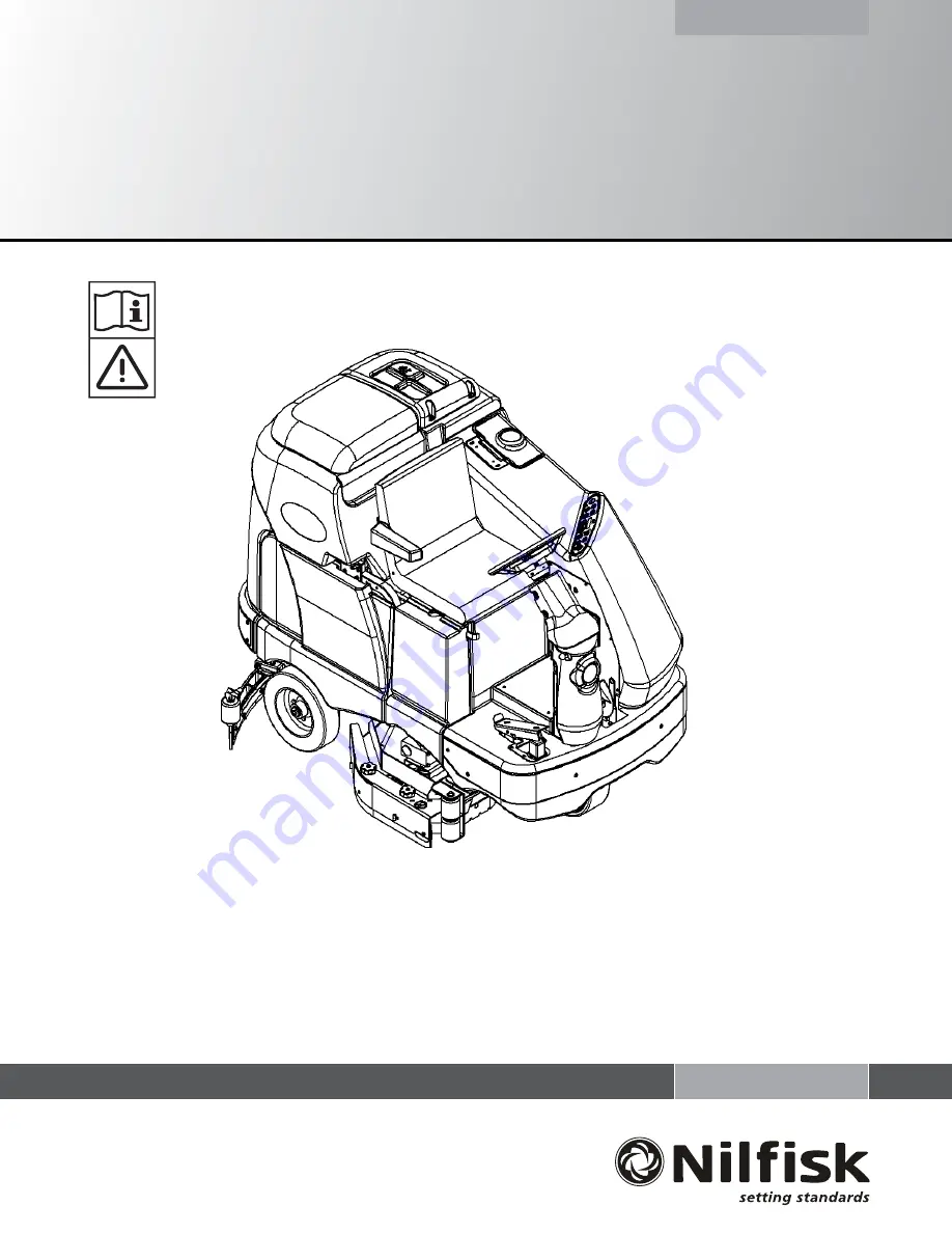
background image

BR 1100S, BR 1300S

Service Manual

11/08 revised 

2

/10 

FORM NO. 56043122

Printed in USA

Models:

56413006(BR 1100S), 56413007(BR 1100S C / w/sweep system), 56413889(OBS / BR 1100S C / w/o sweep system)

56413010(BR 1300S), 56413011(BR 1300S C / w/sweep system), 56413890(OBS / BR 1300S C / w/o sweep system)

56413785(BR 1100S EDS), 56413781(BR 1100S C EDS / w/sweep system), 56413897(OBS / BR 1100S C EDS / w/o sweep system)

56413782(BR 1300S EDS), 56413783(BR 1300S C EDS / w/sweep system), 56413898(OBS / BR 1300S C EDS / w/o sweep system)

Summary of Contents for 56413006

Page 1: ...56413889 OBS BR 1100S C w o sweep system 56413010 BR 1300S 56413011 BR 1300S C w sweep system 56413890 OBS BR 1300S C w o sweep system 56413785 BR 1100S EDS 56413781 BR 1100S C EDS w sweep system 56413897 OBS BR 1100S C EDS w o sweep system 56413782 BR 1300S EDS 56413783 BR 1300S C EDS w sweep system 56413898 OBS BR 1300S C EDS w o sweep system ...

Page 2: ...NAL OVERVIEW 32 VACUUM RECOVERY SYSTEM MAINTENANCE CHECKLIST 33 TROUBLESHOOTING GUIDE 33 MAINTENANCE OF VACUUM SYSTEM FILTER SCREEN AND FLOAT CAGE 33 VACUUM MOTOR REMOVAL 33 RECOVERY TANK REMOVAL 33 SQUEEGEE SYSTEM 35 37 SQUEEGEE SYSTEM LIFT MOTOR OVERVIEW 35 OPERATIONAL OVERVIEW OF THE SQUEEGEE LIFT MOTOR REVERSE FUNCTION 35 SQUEEGEE LIFT ACTUATOR REPLACEMENT 36 SQUEEGEE MAINTENANCE 36 SQUEEGEE A...

Page 3: ...G 55 ACTUATOR DRIVE NUT ADJUSTMENT 56 57 CURTIS CONTROLLER 58 61 FUNCTIONAL OVERVIEW OF MAIN CONTROL BOARD 62 MAIN CONTROLLER ERROR CODES 63 65 MAIN CONTROLLER DIAGNOSTIC SERVICE TEST MODE 66 69 MAIN CONTROL PROGRAMMING OPTIONS 70 76 ELECTRICAL COMPONENT LOCATION 77 WIRING DIAGRAM 78 WIRING SCHEMATIC 79 DETERGENT EDS SYSTEM 80 81 DETERGENT EDS SYSTEM PLUMBING SCHEMATIC 80 DETERGENT EDS SYSTEM PREP...

Page 4: ...ial Number of your machine for future reference MODEL NUMBER ______________________________________________ SERIAL NUMBER ______________________________________________ TRANSPORTING THE MACHINE CAUTION Before transporting the machine on an open truck or trailer make sure that The machine is tied down securely All access doors and covers are secured tape and strap as needed TOWING CAUTION If the ma...

Page 5: ...ar these agents or operate in areas where flammable liquids exist Do not clean this machine with a pressure washer Only use the brushes provided with the appliance or those specified in the instruction manual The use of other brushes may impair safety CAUTION This machine is not approved for use on public paths or roads This machine is not suitable for picking up hazardous dust Do not use scarifie...

Page 6: ...mum Wheel Floor Loading Left Rear 60 N cm2 86 PSI Maximum Wheel Floor Loading Right Rear 56 N cm2 81 PSI Battery Chargers see Electrical System Battery Section Specifications common to deck size BR 1100S BR 1300S Machine Width with Squeegee English 49 in F 57 in H Metric 78cm F 91cm H Scrub Brush Size Disc Diameter 2 20 in 50 8cm 3 17 in 43cm Cylindrical Outside Scrub Brush Diameter inside core is...

Page 7: ...FORM NO 56043122 BR 1100S 1300S 5 SPECIFICATIONS ...

Page 8: ...y required maintenance before storage MAINTENANCE SCHEDULE MAINTENANCE ITEM Daily Weekly Monthly Yearly Charge Batteries X Check Clean Tanks Hoses X Check Clean Rotate the Brushes Pads X Check Clean the Squeegee X Check Clean Vacuum Shut Off Float X Check Clean the vacuum motor foam filter s X Clean Hopper on Cylindrical System X Check Each Battery Cell s Water Level X Inspect Scrub Housing Skirts...

Page 9: ...FORM NO 56043122 BR 1100S 1300S 7 FIGURE 1 ...

Page 10: ...8 FORM NO 56043122 BR 1100S 1300S THIS PAGE INTENTIONALLY BLANK ...

Page 11: ...l Lever B D 12 Side broom Sweep System Raise Lower and auto sweep functions cylindrical only A B D 13 Tilt Steering Mechanism and Seat A B D 14 Optional Accessories headlight safety beacon etc D 15 Main Control Board Special Program Options check all applicable program settings reference SVR Manual 56043122 Example Fault Recall Mode Etc Program as needed 16 Battery Charger Operation D 17 Chemical ...

Page 12: ...just Free Play A B W 40 Drive Pedal Linkage neutral return Torsion Spring A B 41 Steering Chain lubricate tension 1 4 Deflection A B C 42 Steering Column knob plunger spring also Universal Joint Grease A D 43 Rear Wheels bearing wear Tread Wear C W 44 Sweep Debris Tray cylindrical only Rinse C NOTE For additional service information see service manual form number 56043122 and operators manual form...

Page 13: ... pinpoint the location of an item mentioned in the text 1 Recovery Tank Cover 2 Solution Tank Fill Cover 3 Operator s Seat 4 Solution Tank Drain Hose 5 Steering Wheel Tilt Adjust Knob 6 Brake Pedal Parking Brake 7 Solution Shut Off Valve 8 Drive Pedal Directional Speed 9 Hopper cylindrical models only 10 Drive and Steer Wheel 11 Emergency Stop Switch Battery Disconnect 12 Scrub Deck 13 Rear Wheel ...

Page 14: ...Filter 19 Recovery Tank Drain Hose 20 Machine Battery Connector 21 Control Panel 22 Squeegee Tilt Adjust Knob 23 Operator Seat Adjustment Lever 24 Control Circuit Breaker 25 Auxiliary Circuit Breaker 26 Brush Motor Circuit Breaker 27 Side Access Panel 28 Squeegee Height Adjust Knob KNOW YOUR MACHINE ...

Page 15: ...DS models only K Display K1 Solution Flow Indicator K2 Fault Indicator K3 Hour Meter K4 EDS Indicator K5 Battery Indicator K6 Scrub Pressure Indicator K7 Recovery Tank FULL Indicator K8 Battery Low Indicator L Side Broom OFF Switch cylindrical models w side brooms M Scrub Speed Switch KNOW YOUR MACHINE Regular Heavy Extreme Regular Heavy Extreme Scrub Scrub Scrub Scrub Scrub Scrub press 1 time pre...

Page 16: ... time before completing the vacuum delay will turn off the vacuum motor immediately F Solution Switch Press the solution switch and hold for approximately 5 seconds to pre wet the floor Note this must be done prior to pressing the Scrub ON switch D When operating in any 3 of the auto scrub pressure modes both the standard solution and detergent EDS models systems have 3 flow rate presets that coin...

Page 17: ...n selected Both the right and left indictor will be blue when the Extreme scrub mode has been selected Solution System Indicator F This indicator will be blue when the solution system has been enabled and or is turned ON This indicator will be OFF when the solution system has been turned OFF This indicator will flash blue when the solution tank float senses a low solution level Vacuum System Indic...

Page 18: ...s is how the 3 different auto flow volumes are managed Note on the EDS systems the L1 valve is not pulsed it is just turned ON and OFF and a separate solution pump is turn ON and OFF pulsed by the A2 control board s program Note Reference the EDS manual section for its detailed component layout and operational explanation During machine scrubbing the solution system s Auto Mode is pre selected and...

Page 19: ...posal Site and flush the tank with clean water Solution Filter Remove and clean the inline Solution Filter C To access the filter housing for removal work underneath the middle left side chassis solution tank No tools are needed to remove the filter hand tighten only Service Tip The manual solution ball valve shut off handle must be placed in the full OFF position This prevents loss of solution wh...

Page 20: ... the solution outlet hose L off from its valve body barbed fitting 6 Remove the 2 Hex Screws M that secure the valve to the underside of the chassis then pull the valve body to the front separating it from the solution inlet Hose N completing the part removal SOLENOID VALVE DISASSEMBLY AND CLEANING 1 Remove the solenoid valve See the Solenoid Valve Removal section for instructions 2 See Figure 1 4...

Page 21: ...coil circuit The energized K5 contactor pulls in closes its load contact K5 and supplies all the brush motor coils K2 K3 K4 their needed positive circuit input Note The machine must be moving to turn on the scrub brush motor s The A1 speed controller outputs a negative voltage signal from its pin 8 RED WHT wire to the A2 control board pin J1 11 Note The A1 speed control s pin 8 motion output signa...

Page 22: ...cal the scrub system s major electrical components are monitored by the main controller A2 to detect any system function failures error codes The system components covered are the brush motor s M9 M10 M11 brush solenoid s K2 K3 K4 and brush lift actuator motor M2 Detected error codes from the main controller are displayed on the hour meter LED display as they occur Note Reference the Main Control ...

Page 23: ...ub deck 6 Remove bottom lift actuator Hair Pin D then push the Retainer Pin E from its housing and mount bracket holes Next disconnect the actuator wire harness connector Note This will prevent the actuator from being turned on and rising when it is disconnected from its deck mount 7 Reference the correct brush motor wire connections at each individual motor then remove all the wiring from the mot...

Page 24: ...ed edge faces toward the center of the machine Replace the blades as a set if all 4 edges are nicked torn or worn beyond their ability to be adjusted 4 Reinstall the skirt housing assemblies onto the machine and adjust the blade for proper contact to the floor when the brush deck is placed in the scrub position Individual Brush Motor removal 1 See Figure 2 3 Remove the scrub brushes from the Brush...

Page 25: ...juster Collars FF Adjustment Tip The skirts Retainer Knobs AA can be loosened with skirts left on and the Adjuster Collars FF rotated by reaching under the skirt housing 3 Turn the Adjuster Collars FF Up or Down to where the blades just fold over enough when scrubbing that all the waste water is contained inside the skirting NOTE Make small adjustments to obtain good blade wiping Do not lower the ...

Page 26: ... remove the upper Hairpin P then slide the actuator Mount Pin Q from the housing and frame mounting bracket holes allowing the motor to drop down completing its removal 3 See the Actuator Drive Nut Adjustment instructions in the electrical manual section to properly install a new drive nut and to verify its dimensional travel measurements 4 After setting or testing the correct drive nut measuremen...

Page 27: ... wire connections at each individual motor then remove all the wiring from the motor terminals Next locate on the brush deck the motor deck ID identification Resistor Plug F and separate its connector 8 From the left and right front deck supports remove the G 4 hex nuts hex screws and bushings then swing the Pivot Support Arms H away from their mounting holes Special Service Note The removal of bo...

Page 28: ...1 inch wide IdlerArm S with an adjustable wrench to obtain a 1 8 belt deflection at midpoint Then tighten the top Screw L and then remove wrench used to tension belt and finish tightening the bottom arm pivot screw Note Two holes are drilled into the end of the motor mount plate The holes are used to quickly help index the belt tensioning Idler Arm S Position the idler arm between the holes when i...

Page 29: ...deck mount Also notice that the motor may stick to the motor mount be careful as motor will drop watch fingers 7 Turn the motor clockwise to access the motor terminal studs Observe the correct wire connections for reassembly then remove both motor wires 8 The deck assembly needs to be lowered to the lift actuator s maximum down position travel to gain the clearance needed to remove the motor from ...

Page 30: ... hopper drain holes daily 3 Clean drain holes in the solution delivery trough on top of the scrub deck weekly 4 Clean built up dirt from the inside of the scrub brush housing weekly 5 Remove any string wrapped around the scrub brush drive hub and idler hub weekly 6 Remove both the scrub brushes and rotate turn end for end weekly See Scrub Brush Removal and Installation Cyl section 7 Inspect the sc...

Page 31: ... O 2 See Figure 2 10 Remove both side skirt assemblies NOTE The skirts are held in place by two large Knobs AA Loosen these knobs slide the Skirt Assemblies BB forward slightly and then off of the Scrub Deck 3 Loosen the Black Knobs CC on top of the Idler Assemblies DD until they drop down far enough to disengage from the Notches EE and remove 4 Slide the brush into the housing lift slightly push ...

Page 32: ...pivoting mechanical arm linkage assembly Fastened at each end of the arm linkage assembly are two short pieces of chain attached to both side broom assemblies that input the raising and lowering of the side brooms To turn on run the side brooms the operator can press either the ON or OFF Side Broom Control Buttons C L located on the control panel A3 which activates lowers the side brooms in all th...

Page 33: ...essure on the actuator mounts pins in removing the front Clevis Pin C 5 See the Actuator Drive Nut Adjustment instructions in this manual section to properly install a new drive nut and to verify its dimensional travel measurements 6 After setting or testing the correct drive nut measurements follow in reverse the above removal steps to reassemble and reinstall Service Tip Shown in the Electrical ...

Page 34: ...eed the heavier water falls to the bottom of the recovery tank Then at the same time the airflow continues through the tank vacuum fan inlet screen vacuum motor and is exhausted out of the vacuum exhaust hose No wastewater ever actually moves through the vacuum motor just the working air The vacuum system uses a shut off float to prevent the tank from being overfilled and stops any water from bein...

Page 35: ...pulling it out from the recessed housing opening Clean the filter and screen by vacuum or washing them out in warm water Note The filter and screen must be completely dry before reinstalling To inspect the vacuum shut off Float Cage B just lift open the right rear recovery tank cover cage location left rear corner of opening The cage openings slots must be kept free of any debris that can restrict...

Page 36: ...34 FORM NO 56043122 BR 1100S 1300S 4 RECOVERY SYSTEM FIGURE 4 2 ...

Page 37: ...he machine is operated in reverse See Figure 5 1 To get the squeegee tool to lift in reverse the drive pedal must be moved off its neutral or forward position which triggers the needed reverse A1 direction output This battery Pos voltage signal from the reverse throttle wire delivers the required A2 board input to the J1 connector pin 12 YEL RED wire This then activates an internal relay circuit t...

Page 38: ...front of the machine Replace the blade if all 4 edges are nicked torn or worn to a large radius 5 Install the blade following the steps in reverse order and adjust the squeegee To Reverse or Replace the Front Squeegee Blade 1 See Figure 5 2 Raise the squeegee tool off the floor then loosen the 2 Thumb Nuts H on top of the squeegee and remove the squeegee tool from the mount 2 Remove both rear tens...

Page 39: ...FORM NO 56043122 BR 1100S 1300S 37 SQUEEGEE SYSTEM 5 FIGURE 5 2 ...

Page 40: ...n and 0 5V throttle input signals for controller output These controller inputs direction and voltage then energize the internal transistors which selects the motor polarity and also at the same time manages the current and voltage output values to the two separate motor circuits armature field per the percentage of the R1 throttle movement MOTOR OPERATION The motor has 4 terminal connections 2 ar...

Page 41: ...FORM NO 56043122 BR 1100S 1300S 39 WHEEL DRIVE SYSTEM 6 FIGURE 6 1 CIRCUIT BREAKER 3 AMP SWITCH KEY COIL MAIN CONTACTOR Partial ...

Page 42: ... with S2 must also be closed 16 ORN KSI key switch input Battery output powers up controller logic circuits Speed Control TABLE 5 PIN 9 Select 2 A2 input PIN 14 Select 1 A2 input EFFECT LOW 0V LOW 0V Transport Mode Mode 1 HIGH 36V LOW 0V Scrub Mode Mode 2 LOW 0V HIGH 36V Traction Mode Mode 3 HIGH HIGH N A WHEEL DRIVE TROUBLESHOOTING GUIDE Problem Possible Cause Wheel drive motor will not run in fo...

Page 43: ...eer Plate D then remove the chain from the chassis 4 Reassemble parts in reverse order and adjust chain tension so that there is about 3 16 1 4 4 7 6 4mm total deflection with moderate pressure applied at the Mid point F as shown Service Tip Note Use a pry bar or shims between the chassis and steer column to help secure the tension adjustment when tightening the 4 steering column mounting screws M...

Page 44: ...shown 2 See Figure 6 3 Remove the 16 G socket headed cap screws 5 16 x 24 from the rim use a 1 4 Hex drive socket 3 Safely jack up or lift the front of the machine 1 2 inches 25 50 mm and block both front machine corners 4 Locate the 2 tapped holes laid out 180 degrees apart found on the tire rim Thread two 1 4 x 20 hex head screws into the tapped holes then turn the screws equal amounts to push a...

Page 45: ...ON AND REPLACEMENT WARNING Turn the key switch A to the OFF position and disconnect the battery pack by pushing in the emergency disconnect red lever 11 Next set machine parking brake 6 and block both rear wheels so machine can t roll 1 To inspect the carbon brushes Qty 4 for brush wear and length remove the socket head cap Screw M shown in Figure 6 3 using a 1 8 hex wrench then separate the metal...

Page 46: ...hine This is done to separate the chain B from the steer sprocket C 4 Remove in the driver s compartment the false floor plate secured with 3 screws to allow access to the top spindle mounting hardware 5 Remove the bearing dust cap Q cotter pin R and then the castle nut S from the spindle shaft WARNING Never work under machine without safety stands or blocking to support the machine 6 Safely jack ...

Page 47: ...FORM NO 56043122 BR 1100S 1300S 45 WHEEL DRIVE SYSTEM 6 FIGURE 6 5 ...

Page 48: ... of the item AB potentiometer shaft Next remove the pot from the Mount Housing AJ Testing the Potentiometer Note The pot doesn t have to be removed from the housing to test 1 Test the potentiometer using an Ohmmeter the pot specification is 5K Ohms 2 Connect the meter leads to each of the outside connections on the potentiometer The meter should read approximately 5000 Ohms plus or minus 500 Ohms ...

Page 49: ...ng the shaft tighten the Screw AH and Nut AG to secure the setting at the Throttle Lever AI 5 Follow steps 1 2 in reverse order see Potentiometer Removal steps to finish the installation Then test drive the machine for proper speed and FWD REV directional control 6 Service Tip Also confirm the Hourmeter Status Display K is free of the error code 03 drive system fault If error 03 is shown the throt...

Page 50: ...n the screw nut being careful not to pull on the linkage connection to the pot shaft and disturb move its neutral setting To Replace Pedal or Spring 3 Position the torsion spring ends A B as shown This is with the Bushing AO and Screw AM not installed 4 Place the bushing inside the pedal channel pilot it into position using a scratch awl or a pin punch 5 Then pivot press the pedal and insert the s...

Page 51: ...uitable jack underneath the wheel axle and jack up the machine so that the wheel is off the floor approximately 1 inch WARNING Place wood blocking under the rear axle as the machine is only being supported by the jack This is to prevent any accidents or machine damage when the wheel is off 6 Carefully pull the complete wheel brake assembly off the axle If replacing the wheel remove the 4 Nuts H an...

Page 52: ...peration of the brakes 1 Have the parking brake lever released in the off position 2 See Figure 7 3 for the front brake cable M Anchor Connection Adjust cable with a 1 4 of threads exposed as shown and tighten hardware 3 Install a new tie strap to chassis this is used to guide allow a small amount of cable movement There should be about a 1 2 space as shown 4 The left rear brake clevis connection ...

Page 53: ...FORM NO 56043122 BR 1100S 1300S 51 REAR WHEEL SYSTEM 7 FIGURE 7 3 ...

Page 54: ...ove the batteries from their shipping crate and carefully inspect them for cracks or other damage If damage is evident contact the carrier that delivered them or the battery manufacturer to file a damage claim 2 Turn the Master Key Switch A OFF and remove the key 3 Remove the recovery tank from the machine NOTE Disconnect the tether and the vacuum motor wiring and lift the tank straight up and off...

Page 55: ...r cell The standard setting is factory selected and should be used unless the battery manufacturer specifies the higher cutout voltage Special Service Note On all the 36V machines a minimum recharge voltage of 2 13 volts per cell must be reached to allow the scrub brush and solution system to reset function again A 36V battery pack must increase to a 38 6 volt minimum DESCRIPTION OF THE BATTERY CO...

Page 56: ... rubber apron Work in a well ventilated area Do not allow tools to touch more than one battery terminal at a time ALWAYS disconnect the negative ground cable first when replacing batteries to prevent sparks ALWAYS connect the negative cable last when installing batteries CAUTION To avoid damage to floor surfaces wipe water and acid from the top of the batteries after charging CHECKING THE BATTERY ...

Page 57: ... remove them for charging Keep the Batteries Clean Monthly Use a damp cloth to wipe dirt from the top of the batteries Battery terminals must be clean and tight If the tops of the batteries are wet after charging the batteries have probably been over filled or over charged Note If there is acid on the batteries wash the tops of the batteries with a solution of baking soda and water 2 tablespoons o...

Page 58: ... Then connect the alligator clips from the cord adapter red clip to the positive and black to negative to battery connector or battery posts The rocker switch is used to change the motor rotation in setting the correct drive nut dimension Instructions for Squeegee Side Broom Lift Actuator Drive Nut Adjustment 1 See Figure 8 3 Hold onto the Actuator Drive Nut A and press the rocker switch to run th...

Page 59: ... above power cord adapter to help position the spring housing assembly in or out for ease in actuator motor installations 9 Afteradjustingtheactuatorspringhousingdimensions follow the Scrub Brush Lift Actuator Removal Disc or Cylindrical manualsectiontoreassemble Reference Figure 8 5 to correctly mount the top of lift motor to the chassis by model size Service Tip See Figure 8 5 Note the correct o...

Page 60: ...e display shows No Faults Present indicating that the controller has not detected anything out of the norm 3 Put the programmer in test mode and observe the status of inputs and outputs in the forward direction In this example the display shows that the forward input did not activate when forward was selected which means the problem is either in the electronic throttle or the throttle wiring 4 Che...

Page 61: ...FORM NO 56043122 BR 1100S 1300S 59 ELECTRICAL SYSTEM 8 J Ø 4 K Fault Indicator 03 FIGURE 8 7 ...

Page 62: ...ntactor driver overcurrent or field winding shorted 1 Main contactor coil shorted 2 Field winding shorted 3 2 000 00 Main contactor welded 1 Main contactor stuck closed 2 Main contactor driver shorted 3 3 000 000 Motor field winding open 1 Field winding connection open 2 Field winding open 3 4 000 0000 Missing contactor 1 Main contactor coil open 2 Main contactor missing 3 Wire to main contactor o...

Page 63: ...cycle the key switch to clear the fault code 4 Move the drive pedal to operate the throttle The motor should begin to turn in the selected direction If it does not verify the wiring to the controller and the motor The motor should run proportionally faster with increasing throttle If not refer to the DIAGNOSTICS section of this chapter TABLE 1 5 If you are using a programmer put it into the test m...

Page 64: ...r Machine system in this manual for a complete explanation of the machine s operation The secondary function of the main control is to detect any system failures and display an error code on the display panel or store it in the main control board s recall memory mode The error code s are used to help the serviceperson determine the fault and to quickly guide in repairing a specific system malfunct...

Page 65: ...Right brush motor contactor coil overload The contactor K2 on 2 or 3 motor deck is the right motor and the only contactor on a single motor deck Same as 05 K2 coil wire colors are Vio Yel Blu 08 Scrub deck actuator overload Normal current load 1 3 Amps max Current load 6 Amps max current no load 1 4 Amps 1 Check for binding or frozen brush lift linkage and excessive weight on the brush deck 2 Chec...

Page 66: ...coil short to ground 1 Disconnect the K4 coil wiring wire colors Vio Gra Red and check to see if the code disappears yes or no If yes the code disappears replace the brush contactor If no the code does reappear test wiring for a short back to the battery pack ground Repair or replace defective wire 2 If the above test doesn t remove the code substitute a new A2 main control board 24 Center brush m...

Page 67: ...a Vio Grn Orn if defective repair or replace 2 Test for 36V at side broom actuator if 0 Volts replace the main control board A1 39 Auxiliary motor contactor coil open 1 Check for open circuit in the K5 coil and wiring wire colors Yel Brn Blk Orn 2 Test for 36V at the K5 coil if 0 Volts replace the main control board A1 40 K5 Auxiliary motor contactor coil short to ground 1 Disconnect the K5 coil w...

Page 68: ...elease the wand switch its indicator light turns off and the display shows numerous service test mode status callouts see Figure 8 9 for detail description of callout information 6 The function of each switch and indicator is described in the following pages 7 To exit this mode turn the main power key switch to the OFF position CONTROL PANEL A Key Switch B Traction Control Switch C Side Broom ON D...

Page 69: ... Battery Display Status AE The status display will show the units battery pack voltage The display is accurate to within 0 20 volts Therefore the voltage displayed may not correlate precisely to a high accuracy calibrated voltmeter An example of a voltage read out would be 36 7 V Solution Tank Low Level Status AF A solution tank icon is shown with a direction arrow pointing UP or DN The up arrow i...

Page 70: ... be a steady blue if the control senses current flow through the actuator It will flash blue if no actuator current flow is sensed actuator at limit open circuit open output driver The horn switch has no effect in this state When the output is in state 3 the actuator output is turned off and the vacuum LED should be OFF If the vacuum switch was the last switch pressed it is possible to momentarily...

Page 71: ...ol uses Pressing and releasing this switch will alternately turn the multimode output on M2 and off M1 The indicator AD provides the following status information Off Speed control mode 1 is selected transport speed Steady Blue Speed control mode 2 is selected scrub speed Traction Control Switch B This switch is used to toggle the state of the multimode output to the speed control This is used to s...

Page 72: ... perform the following steps 1 Turn the main power switch to the off position 2 Press and hold the scrub on switch 3 While holding the scrub on switch turn the main power key switch to the on position 4 Continue to hold the scrub on switch until the display shows key switch icon 5 The factory default pressures have now been restored 6 Turn the main power key switch to the off position Fault Detect...

Page 73: ...rgent switch the display will show current machine programmed settings scrub deck type scrub deck size detergent mode on off fault detection on off and vacuum motor selection 1 or 2 6 To exit this mode turn the main power key switch to the off position Scrub Deck Down Time Period Adjustment FACTORY DEFAULT 2 SECONDS When scrub on switch is pressed the control unit will automatically lower the deck...

Page 74: ...ght scrub indicator will stop blinking and solution indicator will blink Pressing solution switch will now select solution rate Pressing scrub off switch will save the new setting and move to detergent setting if available 8 On machines equipped with the optional detergent system the display will now show detergent bottle with current setting Detergent indicator will blink Pressing detergent switc...

Page 75: ...and display the key switch icon 9 Then turn the key switch to the off position the new settings will remain in effect until it is changed again Extreme Scrub Setting Adjustment FACTORY DEFAULT SCRUB PRESSURE THREE BAR SOLUTION THREE BAR DETERGENT 0 IF AVAILABLE The extreme scrub pressure solution rate and detergent rate can be programmed depending on its application where a higher solution rate is...

Page 76: ...he display will now show a detergent bottle in the upper left corner indicating the detergent selection mode The detergent indictor light will blink and the scrub off will be turned on 6 Pressing and releasing the detergent switch will now select between a normal detergent bottle icon for showing an activated turned on mode or a detergent bottle with a cross through it showing a non activated turn...

Page 77: ...uum switch 3 While holding the vacuum switch turn the main power key switch to the on position 4 Continue to hold the vacuum switch until the vacuum indicator turns on 5 Release the vacuum switch The display will now show a text message Rec Tank Full Detect Enable or Disable The vacuum indictor light will blink and the scrub off will be turned on 6 Pressing and releasing the vacuum switch will now...

Page 78: ...select between the normal intensity or extra bright intensity levels 7 To save the setting press the scrub off switch The display will show the key switch icon asking the user to reset the machine 8 The new setting will be saved and will remain in effect until it is changed again Turn the key off to exit One Minute Detergent and Solution Pump Purge The optional EDS detergent system has a purge flu...

Page 79: ...er L1 Solenoid Solution M1 Motor Wheel Drive M2 Lift Actuator Brush M3 Lift Actuator Squeegee M4 Lift Actuator Side Broom M5 Motor Assembly Vac M6 Motor Assembly Vac optional M7 Gearmotor Assembly Side Broom cyl models only M8 Gearmotor Assembly Side Broom cyl models only M9 Motor Gearbox Assy disk or Motor Brush cyl M10 Motor Gearbox Assy disk or Motor Brush cyl M11 Motor Gearbox Assy disk or Mot...

Page 80: ... CONTACTOR CENTER BRUSH K3 CONTACTOR CENTER BRUSH 1 2 X6 X6 1 2 3 4 5 6 7 8 9 10 11 12 13 14 15 16 K2 CONTACTOR RIGHT BRUSH K2 CONTACTOR RIGHT BRUSH M M2 BRUSH ACTUATOR M M2 BRUSH ACTUATOR BLK RED M M10 MOTOR CENTER BRUSH LEFT MOTOR ON 2 MOTOR DECKS M M10 MOTOR CENTER BRUSH LEFT MOTOR ON 2 MOTOR DECKS H2 LAMP FLASHING OPTIONAL H2 LAMP FLASHING OPTIONAL 1 2 M M16 PUMP CHEMICAL METERING OPTIONAL M M...

Page 81: ... DISK FOR 40 DISK SP9 SP9 1 2 2 X55 X55 A B S1 SWITCH KEY S1 SWITCH KEY B1 3 H4 HORN H4 HORN 1 2 1 2 H2 LAMP FLASHING OPTIONAL H2 LAMP FLASHING OPTIONAL 1 2 X48 X48 A B A1 A1 S1 S2 B M B X42 X42 A B F1 CIRCUIT BREAKER 3 AMP F1 CIRCUIT BREAKER 3 AMP 1 2 X21 X21 A B SP8 SP8 1 2 2 X14 X14 A B K3 CONTACTOR CENTER BRUSH K3 CONTACTOR CENTER BRUSH 1 2 3 4 H3 LAMP HEAD H3 LAMP HEAD 1 2 GROUND X58 GROUND X...

Page 82: ... Shut Off Valve 3 Inline Solution Filter 4 Solution Pump 5 Detergent Tank 6 Detergent Pump 7 Drain Hose 8 Drain Plug 9 Solution Solenoid Valve 10 Reducer Tee 11 Y Barb Fitting 12 Solution Manifold Disc Models 13 Tee 14 Coupler Barb 9 DETERGENT EDS SYSTEM PLUMBING SCHEMATIC ...

Page 83: ... 2 Turn the Key Switch A ON and press the Detergent Switch J and the Solution Switch F down for at least 2 3 seconds NOTE Once activated the purge process takes 20 seconds See illustration on next page for Detergent System indicators Normally one purge cycle is adequate to purge the system To Purge Weekly 1 Disconnect and remove the detergent cartridge Install and connect a Cartridge filled with c...

Page 84: ...Nilfisk Advance A S Sognevej 25 DK 2605 Brøndby Denmark Tel 45 43 23 81 00 Fax 45 43 43 77 00 www nilfisk advance com ...

Reviews: