

Quick installation guide
1
2
3
1
1. Preliminary steps
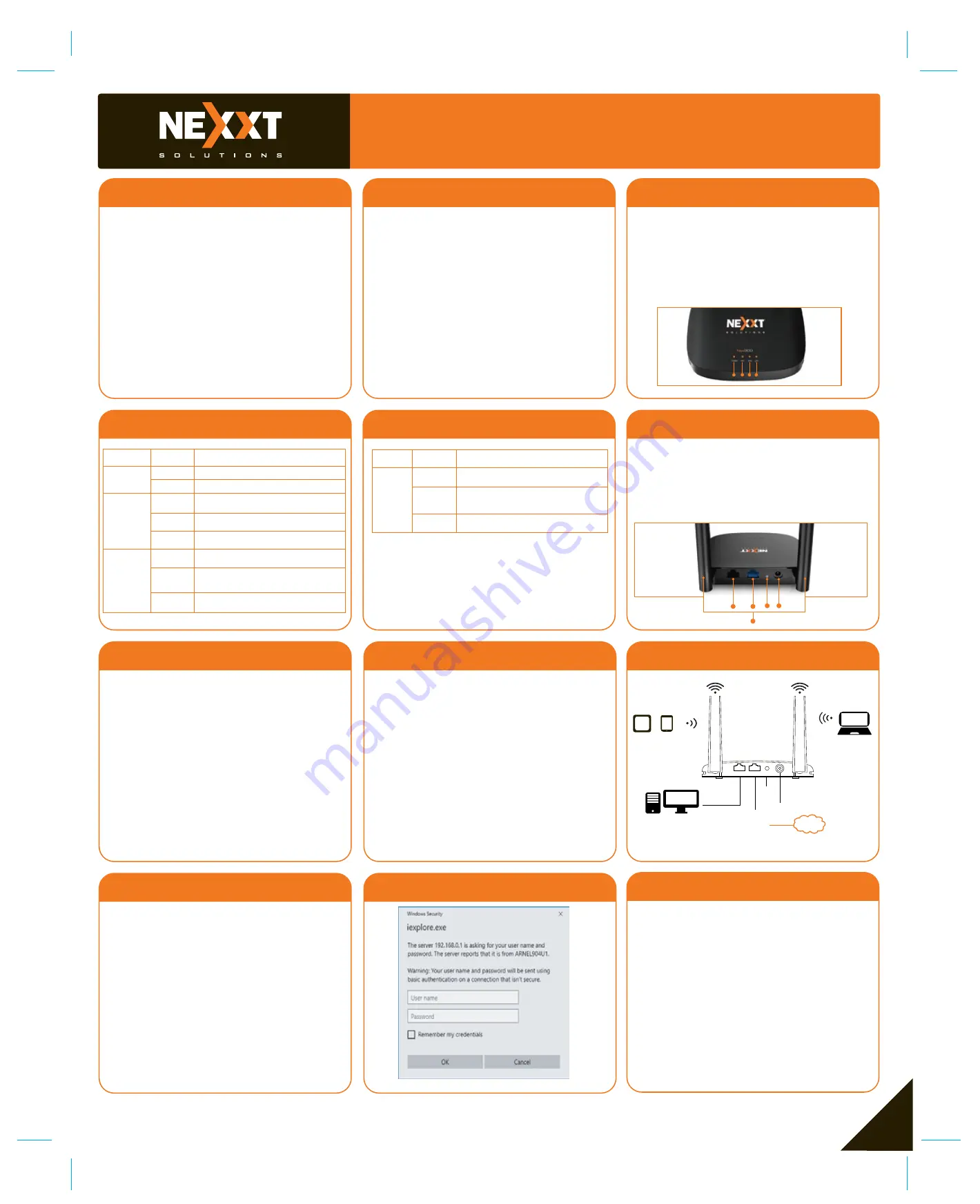
4. Web UI router configuration
2. Product layout
This advanced network device works as wireless router,
universal repeater and access point. Before setting up
the router, you must verify that you have high-speed
internet access available. The most widely used
connection nowadays is broadband DSL or Cable.
The description used in this guide is based on that
type of connection.
1. Antennas:
Two 5dBi omnidirectional antennas
2.
LAN port:
Connect your local laptop or desktop computers
in your network to any of these RJ45 ethernet ports
3. WAN:
This RJ45 port is where you will connect the
DSL/cable modem or Ethernet line from your ISP.
4.
WPS:
Press this button for 3 seconds to connect to the
2.4GHz band and use the WPS feature. (When enabled,
mobile devices will connect to the network directly without
a password).
Reset:
Press and hold this button for at least 5 seconds to
restore the router to its factory default settings.The
router must be powered on in order for this function to
work.
5. DC-IN:
Connect the supplied power adapter to this jack.
1.
First determine the optimum location for the router. The best
place is usually at the center or your wireless network with the
antennas in the upright position.
2.
Then, connect the modem to the WAN port of the router
using the supplied ethernet cable.
3.
Connect your PC to the router if using a wired connection.
4.
Insert one end of the supplied power adapter to the AC input
jack located on the rear panel of the router, before plugging the
other end to a standard electrical wall outlet.
Thank you for purchasing the new Nyx300
wireless- N router from Nexxt Solutions™. If any
of the following items are mismatched, missing
or damaged, please contact the store from
whom you purchased the unit for immediate
replacement.
• Wireless-N router
• Power adapter 110/220V
• Network cable
• Quick installation guide
4
5
6
7
8
10
11
12
9
1.
Open a web browser to access the main web user
interface. Type the default IP address of the router:
192.168.0.1 into the address bar, and then press
Enter on the keyboard.
2.
A popup should come up asking for the username
and password in order to log into the device. The
default username/password is admin in both
instances.
Click OK or press Enter to continue.
3.
The home page will be displayed. In this window the user
can change basic parameters, such as the Network
name (SSID) and the Passphrase. This page also
allows you to change the language to Spanish.
Select your Connection Type and click on Save/Apply
when done. For the purposes of this guide, the
DHCP (Auto Config) option has been selected.
Front panel
3. Hardware installation
LED indicators on the front panel provide information about
network activity, the connection and link status of the ports
in real time. They also facilitate activity monitoring and
troubleshooting the performance of the device.
LED
indicator
Solid The system is working properly
No link is detected on that port
Off
Off
Solid
Blinking
Solid
Blinking
Off
No power is being supplied to the router
The Wi-Fi radio is disabled
The device is actively sending or transmitting
data using wireless link
An ethernet cable is connected in this port
The device is actively sending or
transmitting data over that port
The Wi-Fi radio is working properly
Status
Description
LED
indicator
Status
Description
Power
Wi-Fi
WAN
Solid
Blinking
An ethernet cable is connected in this port
Off
No link is detected on that port
The device is actively sending or
transmitting data over that port
LAN
Internet
*Images herein are for references only. The actual product may differ.
LAN
WPS
Reset
Tablet Phone
POWER
WAN
WAN
LAN
Back panel
The rear panel provides the physical connectors for power
and the client network devices.
2
3
4
5
1.
2.
3.
4.
1
1
1
2
3
4


