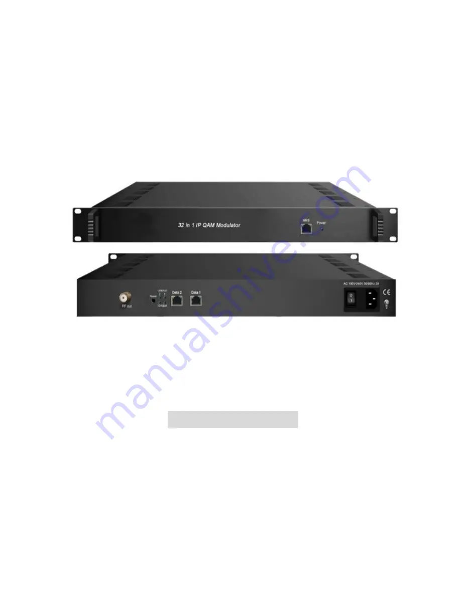
background image

       IP QAM Modulator

User Manual

About This Manual

Intended Audience 

This user manual has been written to help people who have to use, to integrate

and to install the product. Some chapters require some prerequisite knowledge in

electronics and especially in broadcast technologies and standards. 

Disclaimer

No part of this document may be reproduced in any form without the written

permission of the copyright owner.

Summary of Contents for NK3316/32

Page 1: ...lp people who have to use to integrate and to install the product Some chapters require some prerequisite knowledge in electronics and especially in broadcast technologies and standards Disclaimer No part of this document may be reproduced in any form without the written permission of the copyright owner ...

Page 2: ...the product that it is relevant to It cannot be copied modified or translated in another language without prior written authorization from Directory Chapter 1 Product Overview 1 1 1 Outline 1 1 2 Inner Structure 1 1 5 Specifications 2 Chapter 2 Physical Presentational Statement 2 2 1 Front panel Illustration 4 2 2 Rear panel Illustration 4 Chapter 3 Installation Guide 5 3 1 Acquisition Check 5 3 2...

Page 3: ...ormance and low cost This is very adaptable to newly generation CATV broadcasting system 1 4 Key Features 2 GE input SFP interface Supports up to 1024 channels TS over UDP RTP unicast and multicast IGMP v2 v3 Max 840Mbps for each GE input Supports accurate PCR adjusting Supports CA PID filtering remapping and PSI SI editing Supports up to 180 PIDS remapping per channel Support DVB general scrambli...

Page 4: ...0 per channel Functions PID remapping auto manually optional PCR accurate adjusting PSI SI table automatically generating Scrambling Parameters Max simulscrypt CA 4 Scramble Standard ETR289 ETSI 101 197 ETSI 103 197 Connection Local remote connection Modulation Parameters QAM Channel 16 32 non adjacent carrier Modulation Standard EN300 429 ITU T J 83A B Symbol Rate 5 0 7 0Msps 1ksps stepping Const...

Page 5: ...R 40dB ACLR 60 dBc TS output 16 32 IP output over UDP RTP RTSP unicast multicast 2 100 1000M Ethernet Ports System Network management software NMS supporting General Demission 420mm 440mm 44 5mm WxLxH Weight 3kg Temperature 0 45 operation 20 80 storage Power Supply AC 100V 10 50 60Hz or AC 220V 10 50 60Hz Consumption 15 4W 3 ...

Page 6: ...on 2 2 Rear Panel Illustration 1 NMS CAS network management port and CA data port 2 RF output port 3 Reset IP Reset webmaster IP address recover it to default IP address 4 Link Act Indicators 5 Data Input Output 1 2 SFP 6 Power switch 7 AC Power Socket 8 Grounding Chapter 3 Installation Guide 3 4 5 6 7 8 1 2 4 ...

Page 7: ...t part of this chapter Users can also refer rear panel chart during the installation The main steps of the installation include Checking the possible device missing or damage during the transportation Preparing relevant environment for installation Installing NK3316 32 IP Mux Scrambling QAM Modulator Connecting signal cables Connecting communication port if it is necessary 3 2 1 Device s Installat...

Page 8: ... power requires AC power 220V 10 50 60Hz or 110V 10 50 60Hz Please carefully check before running 3 2 3 Grounding Requirement All function modules good grounding is the basis of reliability and stability of devices Also they are the most important guarantee of lightning arresting and interference rejection Therefore the system must follow this rule Coaxial cables outer conductor and isolation laye...

Page 9: ...is located on the right of rear panel and the power switch is on the left of front panel User can plug one end of the power cord to the socket and insert the other end to AC power When the device solely connects to protective ground it should adopt independent way say share the same ground with other devices When the device adopts united way the grounding resistance should be smaller than 1Ω Cauti...

Page 10: ... to confirm they are on the same network segment For instance the PC IP address is 192 168 99 252 we then change the device IP to 192 168 99 xxx xxx can be 0 to 255 except 252 to avoid IP conflict Launch the web browser an input the device IP address in the browser s address bar and press Enter It will display the Login interface as Figure 1 Input the Username and Password Both the default Usernam...

Page 11: ...rs can configure the output TS parameters in this interface Figure 3 Figure 3 Output TS X From the menu on up side of the webpage clicking Output TS X it displays the interface as Figure 4 Users can select the output TS channels User can click any item here to enter the corresponding interface to check information or set the parameters 9 ...

Page 12: ...igure 5 Figure 5 Configure Input Area and Output Area with buttons in Operation Area Instructions are as below Enable disable the CA Filter function Clicking the box user can filter the input CA to avoid disturbing with the device scrambling function To enable disable the PID remapping To refresh the input program information To select output TS channel 1 16 Input Area Output Area Operation Area 1...

Page 13: ...To select all the output programs To parse programs time limitation of parsing input programs Program Modification The multiplexed program information can be modified by clicking the program in the output area For example when clicking it triggers a dialog box Figure 6 where users can input new information Figure 6 General From the menu on up side of the webpage clicking General it displays the in...

Page 14: ...8 Figure 8 PID Pass From the menu on up side of the webpage clicking PID Pass it displays the interface where to add the PIDs which need pass through Figure 9 Figure 9 Parameters Scrambler From the menu on left side of the webpage clicking Scrambler it displays the interface where users can choose the programs to scramble Figure 10 12 ...

Page 15: ...tput parameters Figure 11 This field indicates the current outputting programs The programs selected will be scrambled Scramble channel select carrier select CA channel select EMMG and ECMG working state green means it work normally while red means communication error or no communication Click to set each channel RF QAM output parameters Click to set all channels RF QAM output parameters 13 ...

Page 16: ...upports TS to output in IP 16 32 MPTS format through the DATA port Click IP Stream it will display the interface as Figure 12 where to set IP out parameters Figure 12 System Network Click Network it will display the interface as Figure 13 where to set network parameters 14 ...

Page 17: ...e clicking Password it will display the screen as Figure 14 where to set the login account and password for the web NMS Figure 14 System Configuration From the menu on left side of the webpage clicking Configuration it will display the screen as Figure 15 where to set your configurations for the device 15 ...

Page 18: ...on left side of the webpage clicking Firmware it will display the screen as Figure 16 where to update firmware for the device Figure 16 System Log From the menu on left side of the webpage clicking Log it will display the screen as Figure 17 where to check the Log Select areas 16 ...

Page 19: ...s Prevention Measure Installing the device at the place in which environment temperature between 0 to 45 C Making sure good ventilation for the heat sink on the rear panel and other heat sink bores if necessary Checking the input AC voltage within the power supply working range and the connection is correct before switching on device Checking the RF output level varies within tolerant range if it ...

Page 20: ...cuit short Device in damp environment Device was suffered from physical damage Longtime idle After switching on and restoring to factory setting device still cannot work properly Maintenance needed Chapter 6 Packing list NK3316 32 IP QAM Modulator 1 pc User s Manual 1 pc Power Cord 1 pc 18 ...

Reviews: