Neoway N723-EA, Hardware User'S Manual
The Neoway N723-EA Hardware User's Manual is a comprehensive guide that provides detailed instructions for operating and optimizing the device. This essential manual is available for free download from our website, ensuring easy access for users to unleash the full potential of their Neoway N723-EA. Get yours today!
Share
Download


Reviews:
No comments
Related manuals for N723-EA
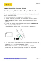
Elite 65e
Brand: Jabra Pages: 2
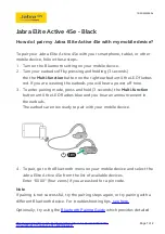
Elite Active 45e
Brand: Jabra Pages: 2

JBL Under Armour SPORT WIRELESS FLEX
Brand: Harman Pages: 24

NWA1000 Series
Brand: ZyXEL Communications Pages: 263

WTS-6KW-3P
Brand: wattsonic Pages: 60

BR182n
Brand: E-TOP Pages: 93

DM984-100B
Brand: Datacom Pages: 105

BTH16
Brand: iClever Pages: 12

AP400 series
Brand: NEC Pages: 4

AP-3
Brand: Avaya Pages: 425

WLAN Access Port 223x
Brand: Nortel Pages: 46

Wireless EZ-Bridge AC
Brand: Tycon Power Systems Pages: 20

APX-3100
Brand: AAxeon Pages: 14

4G LTE
Brand: Novatel Pages: 96

CMM-9301-V3.1S
Brand: C-Max Pages: 9

MiFi 4620L
Brand: Novatel Pages: 79

IAHRF79
Brand: iLive Pages: 16

N-WAP
Brand: LEGRAND Pages: 65


