NCR 7610-K41, Instructions Manual
The NCR 7610-K41 is a high-quality and user-friendly point-of-sale terminal. For detailed setup and operation procedures, download the Instructions Manual for free from manualshive.com. This comprehensive manual will guide you through maximizing the performance of your NCR 7610-K41, ensuring a seamless retail experience for both you and your customers.
Share
Download


Reviews:
No comments
Related manuals for 7610-K41

SprinklerSense WM
Brand: INFLUX MEASUREMENTS Pages: 2
COMPONENT CABLE LUXURY COMPONENT CABLE FOR...
Brand: GAMERON Pages: 32

AD103
Brand: Oregon Scientific Pages: 2

42/12490-00
Brand: ELCART Pages: 2

HDTV-142
Brand: Gefen Pages: 8

Lanscape Solutions CLSSC-03U
Brand: CORNING Pages: 4

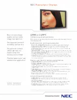
50XR4
Brand: NEC Pages: 10

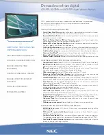
42VP5
Brand: NEC Pages: 28
42VP5
Brand: NEC Pages: 2
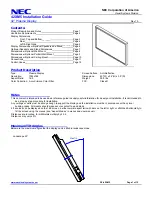
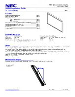
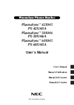
42XM5 - PlasmaSync - 42" Plasma Panel
Brand: NEC Pages: 2

42VP5
Brand: NEC Pages: 12
42XM5 - PlasmaSync - 42" Plasma Panel
Brand: NEC Pages: 12

42XR3
Brand: NEC Pages: 11
50XM5A
Brand: NEC Pages: 10

42XR3
Brand: NEC Pages: 2

50XR4
Brand: NEC Pages: 111

50XR5
Brand: NEC Pages: 140
42XM5 - PlasmaSync - 42" Plasma Panel
Brand: NEC Pages: 203


