NCR 7403 K321, Kit Instructions
The NCR 7403 K321 is a high-quality kit designed for easy installation and use. Download the free manual from manualshive.com for comprehensive instructions on how to set up and operate your product. This user-friendly manual ensures a smooth experience from start to finish.
Share
Download


Reviews:
No comments
Related manuals for 7403 K321

Silver Series
Brand: Iconasys Pages: 3
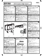
MultiSync P701
Brand: NEC Pages: 2

2247
Brand: NCR Pages: 12

Mountlogic BT8223
Brand: B-Tech Pages: 20

AS2000HS
Brand: Sealey Pages: 2

7403 K141
Brand: NCR Pages: 12

45506019
Brand: GameKeeper Pages: 13

K2-JACK
Brand: L-Acoustics Pages: 4

K1C250
Brand: CHIEF Pages: 12

HPP271MOUNTINGSET1
Brand: Vaisala Pages: 2

122-3491
Brand: RackSolutions Pages: 4

VTM27
Brand: Sanus Pages: 2
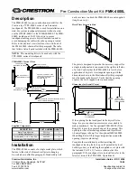
PMK-4000L
Brand: Crestron Pages: 2

5URAIL-2900-EARS
Brand: Rackmount Pages: 4

SK 2
Brand: tecalor Pages: 24

ST-43HF
Brand: LG Pages: 16

KDR-52SX4B
Brand: LG Pages: 1

LSW420BX
Brand: LG Pages: 8


