background image

Trailer connections. 

Both the tractor and trailer have a seven-terminal trailer 

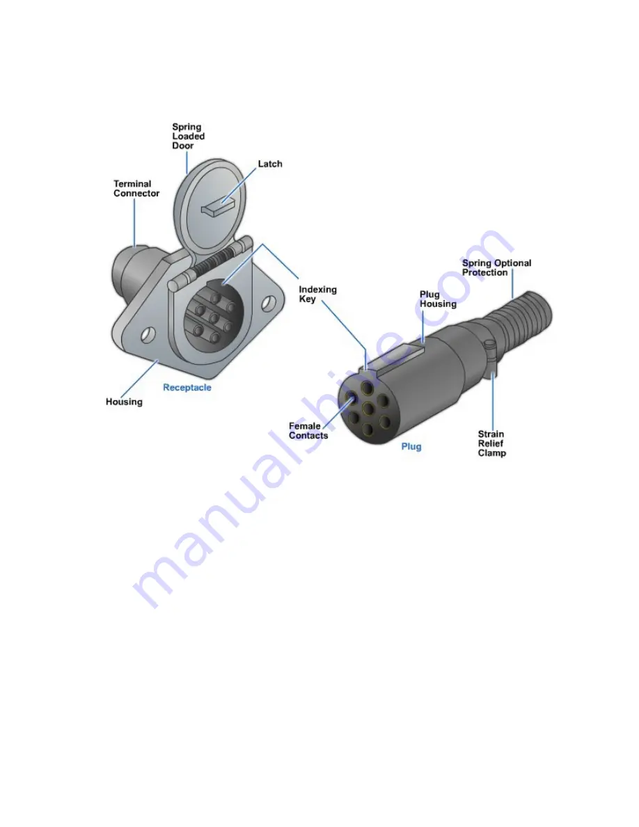
receptacle that accepts the trailer electrical cable plug (

Figure 6-54

). Trailers used as a 

part of double and triple trailers have trailer receptacles at both the front and rear of the 
trailer to provide interconnection between trailers and dollies.


Figure 6-54 - Tractor-trailer connectors.


Because most tractors do not pull the same trailer all the time, the trailer receptacle and 
cable are standardized throughout North America. The trailer interconnection is defined 
by SAE recommended practice J560. Each of the seven circuits on all trucks and 
trailers should be wired in the prescribed manner to permit tractors and trailers 
throughout North America to be interchangeable.


NAVEDTRA 14050A


6-53


Summary of Contents for 14050a

Page 1: ...erconnection between trailers and dollies Figure 6 54 Tractor trailer connectors Because most tractors do not pull the same trailer all the time the trailer receptacle and cable are standardized throughout North America The trailer interconnection is defined by SAE recommended practice J560 Each of the seven circuits on all trucks and trailers should be wired in the prescribed manner to permit tra...

Page 2: ...ustration of the trailer plug and the trailer receptacle in Figure 6 57 is something that you should become familiar with It shows the views of the mating end of the tractor receptacle and of the trailer plug A test light or a special trailer light test tool is used to test for voltage at the specific terminal to determine if the problem is with the truck or the trailer Notice the larger diameter ...

Page 3: ...o Color Key Lamp and Signal Circuits 1 White Ground return to towing vehicle 2 Black x Side marker and identification lamps 3 Yellow Left hand turn signal and hazard signal 4 Red Stop lamps and antilock devices 5 Green Right hand turn signal and hazard signal 6 Brown Tail combined rear clearance and license plate 7 Blue AUx Auxiliary option lamps dome etc Figure 6 56 Schematic layout of a trailer ...

Page 4: ...Figure6 57 Tractorandtrailermatingends Figure 6 58 Trailer power distribution module NAVEDTRA 14050A 6 56 ...

Page 5: ...Figure6 59 TrailerPDMinstallation NAVEDTRA 14050A 6 57 ...

Page 6: ...10 10 10 10 10 10 10 8 8 10 10 8 8 10 8 8 8 8 8 8 8 8 8 8 6 25 12 10 8 8 8 6 6 30 12 10 8 8 8 6 6 35 12 10 8 8 6 6 6 Recommended minimum wire gauge for stop light and ground circuits STOP LIGHT Red GROUND White Single trailer up to 50 length Doubles trailer 2 28 lengths Doubles trailer 2 40 lengths Triples trailer 3 28 lengths 12 Gauge 12 Gauge 10 Gauge 10 Gauge 10 Gauge 10 Gauge 8 gauge 8 gauge F...

Page 7: ...minal connection s damaged wire Trace the suspect circuit Figure 6 61 Quick reference electrical troubleshooting 11 5 1 Horns The horn system uses a coil operated diaphragm to produce sound waves and an audible sound The horn system is simple it consists of 1 Fuse or circuit breaker electrical safety device that protects horn circuit from shorts 2 Horn wiring harness wires that connect fuse to har...

Page 8: ...When the driver releases the horn button a spring pushes the switch back open This breaks or disconnects the ground circuit No current can then flow through the horns and they stop sounding Horn nomenclature A cutaway view of a typical horn is given in Figure 6 63 It is made up of the following components 1 Horn coil set of windings thatproducemagneticfield whenenergizedbycurrent flow Figure6 63 C...

Page 9: ...quency of the diaphragm vibration Horn relay A horn relay is sometimes used between the horn switch and the horns It is used to reduce the amount of current flowing through the horn switch When the driver presses the horn switch a small current flow enters the horn relay This energizes the small coil in the relay to close the relay contacts Then a larger current flows through the closed relay poin...

Page 10: ...heck for power going to the motor If the test light does not glow the wiper switch may be bad When working on a windshield wiper system always follow the exact recommendations given by the manufacturer as systems and procedures vary with each vehicle Normally the wiper motor must be replaced as a unit The transmission gears are usually the only serviceable part in the assembly 11 6 2 Windshield Wa...

Page 11: ...er window is shown in Figure 6 64 Some power windows will stop or reverse direction if an obstruction resists window closing In some of these systems a magnetic trigger wheel is mounted on the motor s armature shaft As the trigger wheel turns it creates a signal in a magnetic or Hall effect sensor in the motor assembly If the sensor outputs a slower than normal signal the power windows ECM will cu...

Page 12: ... electronic devices can be found almost everywhere on an automobile truck power generation equipment and construction equipment These components have even replaced some mechanical devices They are more efficient compact and lighter Troubleshooting equipment takes complex diagnostic procedures much service literature and specialized equipment It is uncommon for the mechanic to get through even one ...

Page 13: ...ings mounted between the end frames A True B False 4 There are commonly two types of bearings used in an alternator one being ball type What is the other type of bearings sometimes used A roller thrust B roller C friction D needle 5 The text lists three types of alternator belts Which of the following is not an alternator belt A ribbed V belt B conventional V belt C ribbed belt D cogged V belt 6 W...

Page 14: ...o the rotor windings B Preventing more current into the rotor windings C Allowing less current into the rotor windings D Allowing more current into the stator windings 10 Field circuit modulation refers to how the can cycle the rotor field current on and off to control charging system output A stator B diode trio C voltage regulator D rectifier bridge 11 True or False It is not necessary to discon...

Page 15: ...When using an ohmmeter to test diodes what must you do A Connect the diodes with a piece of wire B Remove the diodes from the alternator C Disconnect the stator windings D Unsolder the diodes and isolate them 16 When testing a diode with an ohmmeter and it reads high resistance in one direction and low resistance in the other what does this reading tell you A The diode is good B The diode is short...

Page 16: ...onent of the ignition system boosts battery voltage to a much as 60 000 volts A Alternator coil B Ignition switch C Ignition coil D Battery booster 22 True or False An electronic ignition is more dependable than a contact point because there are no mechanical breakers to wear or burn A True B False 23 A solid state chip or module that produces an electrical signal when triggered by a slotted wheel...

Page 17: ...gnition system what test compares actual resistance or voltage output A Magnetic pickup coil B Ignition coil C Electronic ignition resistance D Magnetic voltage 29 When conducting a Hall effect sensor with an oscilloscope how should the waveform appear A Switch slowly angled sides top square reaching reference voltage and bottom should reach zero B Switch rapidly sloped sides top rounded reaching ...

Page 18: ...ost fuses are designed to maintain what percent of overload current indefinitely A 105 B 110 C 115 D None of the above 35 True or False Blade fuses come in three sizes sometimes referred to by their trade names They are Mini fuse auto fuse and Maxi fuse A True B False 36 Trucks will have large bolt in type fuses that are commonly used to protect main battery power feed cable that supplies what A T...

Page 19: ...Solid state C Bimetallic D Electronic 41 The brake light switch is normally mounted on the brake pedal but can also be mounted at what other location A Master cylinder B Brake line C Steering column D Both A and B 42 The color of wiring insulation is standardized What color is the wire for the STOP lamps and antilock devices A Red B Green C Brown D Blue 43 The tractor normally provides the circuit...

Page 20: ...n A 2 3 B 3 4 C 4 5 D 5 6 47 After making all the required checks on the windshield washer and determining that the pump is bad what is the next step A Rebuild the pump B Replace the pump C Repair the pump D Tap on the pump 48 When troubleshooting an inoperative power window you can hear a humming noise where the motor is spinning but there is no movement of the window What may be the problem A St...

Page 21: ...ern Automotive Technology 7th Edition James Duffy The Goodheart Wilcox Company Inc 2009 ISBN 978 1 59070 956 6 Auto Engine Performance and Drivability Chris Johanson The Goodheart Wilcox Company Inc 2004 ISBN 1 59070 257 3 Automotive Technology A Systems Approch 4th Edition Jack Erjavec Thomas Delmar Learning 2005 SBN 1 4018 4831 1 Auto Electricity and Electronics James Duffy The Goodheart Wilcox ...

Page 22: ...e write or email us using this form or a photocopy Be sure to include the exact chapter number topic detailed description and correction if applicable Your input will be brought to the attention of the Technical Review Committee Thank you for your assistance Write CSFE N7A 3502 Goodspeed St Port Hueneme CA 93130 FAX 805 982 5508 E mail CSFE_NRTC navy mil Rate_ Course Name Revision Date Chapter Num...

Page 23: ...on the operation and repair of specific units refer to the specific manufacturer s maintenance and repair manual Objectives When you have completed this chapter you will be able to do the following 1 Understand the principles of and how to troubleshoot clutch systems 2 Understand the principles of and how to troubleshoot automatic transmissions Prerequisites This course map shows all of the chapte...

Page 24: ...appropriate definition Audio and video clips are included in the text with italicized instructions telling you where to click to activate it Review questions that apply to a section are listed under the Test Your Knowledge banner at the end of the section Select the answer you choose If the answer is correct you will be taken to the next section heading If the answer is incorrect you will be taken...

Page 25: ... disc and a matching external set on the clutch shaft They permit the friction disc to slide back and forth along the shaft but force the disc and the shaft to rotate together Figure7 1 Singlediscclutch The flywheel attached to the end of the engine crankshaft rotates when the engine is running When the clutch is engaged in the coupling position the friction disc is held tightly against the flywhe...

Page 26: ...ions The hydraulic operating system Figure 7 5 moves the release lever by hydraulic pressure Depressing the clutch pedal creates pressure in the clutch master cylinder actuating the slave cylinder which in turn moves the release arm and disengages the clutch Hydraulic types of clutch operating systems are normally found in heavy construction equipment where extreme pressure is required to operate ...

Page 27: ...o the driving wheels through the power train The double disc clutch is Figure7 6 Double discclutch substantially the same as the single disc clutch described in the section above except that an additional driven disc and intermediate driving plate are added 1 1 0 Clutch Malfunctions The information given in this section is general and may be applied to nearly every type of clutch you are likely to...

Page 28: ...ch slippage To solve this problem free up the linkage that is binding by simply lubricating or aligning the clutch linkage If this fails to correct the problem you may have to remove the clutch for further inspection and repair Riding the clutch is an operator problem whereby the operator steadily drives with a foot on the clutch pedal As a result the pedal may be partially depressed and cause clu...

Page 29: ...lving noise and necessitating disc replacement is loose or weak torsional springs surrounding the disc hub You may also find that the antirattle springs on the pressure plate assembly are weak and require replacement A hose or misaligned transmission will cause noisy clutch operation You can easily correct this by loosening the transmission shifting it into proper alignment and retightening it 1 1...

Page 30: ...hift control lever position and vehicle speed It relieves the operator of the responsibility of selecting the best possible gear ratio for each condition and makes driving easier and safer Figure 7 7 Automatic transmission Many different models of automatic transmissions are manufactured today Automotive applications usually have three speeds forward and one reverse More recently the automotive in...

Page 31: ...d gear set it couldnot keep up with the demands of the rising fuel prices Along came some new additions to the transmission world the 4L60 4L80 4L80E and the Allison These transmissions were based off the ever popular TH400 but had a kick overdrive The 4L80E Figure 7 8 is a truck automatic transmission that was introduced by GM in the early 1990s It basically uses many of the same internal compone...

Page 32: ...crease in the speed of the output member proportional to the increase in the output of torque This means that with a constant input speed the output torque increases as the output speed decreases Figure 7 9 Planetary gearset operation Reduction can be obtained in several ways In a simple reduction the sun gear is held stationary and the power is applied to the internal gear in a clockwise directio...

Page 33: ... engine speed whenever the engine is operating Figure7 10 Torqueconverter Figure7 11 Torqueconverter operation When the engine is running and the converter pump is spinning Figure 7 11 it acts as a centrifugal pump picking up oil at the center and discharging this oil at its rim between the blades The shape of the converter pump shells and blades causes this oil to leave the pump spinning in a clo...

Page 34: ...y on its shaft Once the stator becomes inactive there is no further multiplication of engine torque within the converter At this point the converter is merely acting as a fluid coupling as both the converter pump and the turbine are turning at the same speed or at a 1 1 ratio 2 4 1 Hydraulic System Operation The hydraulic system has five basic functions 1 The planetary holding devices are all actu...

Page 35: ...like it is when the transmission is in park AFL oil is sent to the pressure control solenoid and continues to regulate line pressure but has no effect on the shift valves In neutral the manual valve is positioned to cut off the oil flow to the low reverse clutch piston and no holding members are applied in neutral 2 4 3 Drive First Gear When the transmission is placed in drive with the vehicle not...

Page 36: ...he transmission is now in third gear 2 4 6 ve Fourth Gear When enough speed is attained and other sensor inputs are correct the ECM decides that the transmission should be shifted into fourth gear The ECM energizes the 1 2 shift solenoid sealing the exhaust passage in the solenoid The 2 3 shift solenoid remains de energized With the 1 2 shift solenoiod back on AFL oil pressure can build up on the ...

Page 37: ...stly overhaul Overfilling the transmission can result in the fluid foaming and the fluid being driven out through the vent tube The air that is trapped in the fluid is drawn into the hydraulic system by the pump and distributed to all parts of the transmission This situation will cause air to be in the transmission in place of fluid and in turn cause slow application and burning of clutch plates a...

Page 38: ...first Service intervals depend on the type of use the vehicle receives In the NCF because of the operating environment more than a few of the vehicles are subjected to severe service Severe service includes the following hot and dusty conditions constant stop and go driving taxi service trailer towing constant heavy hauling and around the clock operations contingency Any CESE operating in these co...

Page 39: ... 2 5 1 4 Refilling the Transmission Reinstall the transmission oil pan the oil plug and the fill tube Fill the transmission with the fluid prescribed by the manufacturer to the proper level With the brakes applied start the engine and let it idle for a couple of minutes Move the gear selector through all gear ranges several times allowing the fluid to flow through the entire hydraulic system to re...

Page 40: ...checking an electronically controlled transmission see if you can get a trouble code from the ECM 2 5 2 3 Determine Which Component is the Most Probable Cause Using you knowledge of transmissions determine if the problem is due to the mechanical system the hydraulic system or the electrical system 2 5 2 4 Perform Pinpoint Tests This step takes the most time You need to check each system and look a...

Page 41: ...est but this is not always available Obtain the cleanest work space possible Have on hand any special tools needed for the job such as snap ring pliers torque wrenches or special pullers It is also a good idea to have an air compressor available for test purposes and for blowdrying individual parts The steps listed below are common procedures listed for a generic automatic transmission and may not...

Page 42: ...Figure7 15 Transmissionina cradle 7 Remove the bolts holding the extension housing to the case Extension housings are sometimes called tailshaft housings The extension housing should pull off over the output shaft after the bolts are removed 8 Remove the governor This step only applies to governors mounted on the output shaft 9 Remove the front oil pump oil seal Figure 7 16 It is generally easier ...

Page 43: ...r internal parts can be removed 13 Some transmissions have a center support Figure 7 18 It may be retained by one or two case bolts located either inside or outside the case These must be removed before you can remove the center support and the rear clutches and gearsets 14 Remove any servos accumulators clutch apply pistons and governors NOTE Many servos and accumulators are under strong spring p...

Page 44: ...otive automatic transmissions and only specific instructions for that particular unit will be different For these specific instructions go to your technical library and check out the correct repair manual Test your Knowledge Select the Correct Response 2 The automatic transmission of a vehicle matches power and speed to what factor A RPM B Maximum torque C Load requirements D Minimum torque requir...

Page 45: ... noticeable during which of the following conditions A When the vehicle is cold B When the vehicle is hot C When the vehicle is heavily loaded D When the vehicle is traveling at high speeds 5 When you notice insufficient clutch pedal free travel you should check which of the following items A The linkage for proper adjustment B The release bearing for wear or dryness C The friction disc facing for...

Page 46: ... greater gear reduction C To reduce gear clash D To increase torque 9 When torque is increased during the operation of a planetary transmission what will happen to the output speed A It will remain the same B It will increase C It will decrease 10 Your holding the sun gear stationary and applying power to the internal gear in a clockwise direction will produce what result in gearing A Overdrive B ...

Page 47: ...problems A Hardshifting B High line pressure C Slow application of the clutch packs D Low torque output 17 Water mixed with automatic transmission fluid will turn the fluid what color A Brown B Milky C Pink D Clear 18 True or False Rags are an acceptable item to dry a screen in an automatic transmission A True B False 19 Which of the following methods should you use to remove air trapped in a tran...

Page 48: ...Unnecessary equipment down time only D Severe parts damage and unnecessary equipment down time 22 During an automatic transmission overhaul an air compressor is used for which of the following purposes A To conduct tests B To blow dry parts C Both A and B D To disassemble clutch packs 23 When you disassemble an automatic transmission you must remove what component before removing the valve body A ...

Page 49: ...Trade Terms Introduced in this Chapter Coupling To join the engine with the transmission Uncouple To separate the engine and transmission NAVEDTRA 14050A 7 27 ...

Page 50: ...lmar Cengage Learning 2006 ISBN 13 978 1 4018 7064 5 Modern Automotive Technology 7th Edition James Duffy The Goodheart Wilcox Company Inc 2009 ISBN 978 1 59070 956 6 Automatic Transmissions and Transaxles James Duffy The Goodheart Wilcox Company Inc 2005 ISBN 1 59070 426 6 Manual Drive Trains and Axles Chris Johanson James Duffy The Goodheart Wilcox Company Inc 2004 ISBN 1 59070 320 0 Power train...

Page 51: ...e write or email us using this form or a photocopy Be sure to include the exact chapter number topic detailed description and correction if applicable Your input will be brought to the attention of the Technical Review Committee Thank you for your assistance Write CSFE N7A 3502 Goodspeed St Port Hueneme CA 93130 FAX 805 982 5508 E mail CSFE NRTC navy mil Rate Course Name Revision Date Chapter Numb...

Page 52: ...ere even in military vehicles the construction mechanic still must be accomplished in the troubleshooting and overhaul of the standard transmission The next topic covers the transfer case which is found on a great number of military type vehicles It can be said it is as common as the transmission since there are so many 4x4 or 6x6 vehicles Troubleshooting the power takeoff is another topic The pow...

Page 53: ... D V A N C E D Air Compressor Overhaul Inspecting and Troubleshooting Brake Systems Hydraulic Systems Wheel and Track Alignment Troubleshooting Transmissions Transfer Cases and Differentials Clutches and Automatic Transmissions Troubleshooting Electrical Systems Fuel System Overhaul Engine Troubleshooting and Overhaul The Shop Inspectors Alfa Company Shop Supervisor Public Works Shop Supervisor Fe...

Page 54: ...a in the chapter where the information is for review When you have completed your review select anywhere in that area to return to the review question Try to answer the question again Review questions are included at the end of this chapter Select the answer you choose If the answer is correct you will be taken to the next question If the answer is incorrect you will be taken to the area in the ch...

Page 55: ...be informative but if the mechanic drives the road test can be more effective Troubleshooting should always begin with information gathering Next you will have to analyze the information and attempt to identify a root cause Nothing is more helpful than experience with troubleshooting and knowledge Noisy Operation This complaint is common and can be caused by so many different things that you shoul...

Page 56: ...wellsonthegear teethcausedbyimproperhandling Rattles Metallic rattles within the transmission result from a variety of conditions Engine tensional vibrations are transmitted to the transmission through the clutch In heavy duty equipment featuring clutch discs without vibration dampers rattles may result that are most noticeable in neutral In general engine speeds should be 600 rpm or above to elim...

Page 57: ...tions that can cause noise in neutral Difficult to shift Difficult to shift is a condition that occurs when the shift lever is difficult to move from gear to gear In some instances only one gear is hard to select in others all shifting may be difficult The usual causes of hard shifting are bent or worn shift linkage and linkage in need of lubrication Hard shifting may also be caused by binding of ...

Page 58: ...izers Other problems inside the transmission can cause it to jump out of gear They include worn synchronizer inserts and springs worn shift fork assemblies or shift rails and wear and excessive play in the countershaft and output shaft assemblies Locked in gear When the shifter is locked in one gear check the transmission shifter assembly and linkage Look for bent shift rods worn linkage bushings ...

Page 59: ...nchronizer Slips or jumps out of gear 1 Transmission loose or misaligned 2 Clutch housing loose or misaligned 3 Shift linkage improperly adjusted 4 Shift rail detents worn or detent springs weak 5 Synchronizer clutch sleeve teeth worn 6 Loose shifter cover 7 Shift fork shaft or levers worn 8 Worn teeth on main drive gear or other gears 9 Worn countershaft gear assembly bearings and or thrust washe...

Page 60: ...amaged gears 4 Wrong lubricant 5 Excessive synchronizer wear 6 Defective speedometer gears 7 Transmission misaligned 8 Excessive input or output shaft and or countershaft gear endplay 9 Contaminated lubricant 1 Fill to filler plug 2 Replace bearings 3 Replace gears 4 Drain and fill with recommended lubricant 5 Replace synchronizer 6 Replace gears 7 Correct alignment 8 Adjust endplay 9 Disassemble ...

Page 61: ...he shaft to check for wear If excessive movement is found remove the clutch release mechanism and check for worn bushings COE remote shift linkage Check the linkage U joints for wear and binding Lubricate the U joints Check any bushings in the linkage for wear Air filter Check and clean or replace the air filter element Transmission output yoke 10 Uncouple the U joint and check the flange nut for ...

Page 62: ... A leaking rear main seal can lead to complete transmission failure so it must be repaired It can be difficult to source oil leaks on transmissions however so be sure to identify the leak path before disassembling any components You can use a checklist such as the following to help you identify the source of oil leaks but it is most important before beginning to pressure wash the transmission remo...

Page 63: ...r gaskets and thoroughly clean the fasteners and their mating threads before reinstalling 6 Check the cover plates and manifolds bolted to the transmission housing for cracks or breaks including the front bearing cover plate front housing shift bar housing rear bearing cover and the clutch housing All of these components can be a source of oil leaks 7 Check the front bearing cover plate Oil return...

Page 64: ... elsewhere For example with the engine running and the vehicle standing still disengage the clutch and move the gearshift lever into first or reverse You should be able to shift into either of these gear positions without any gear clashing or without the vehicle moving If the gears clash or the vehicle attempts to move with the clutch disengaged the trouble is in the clutch and not the transmissio...

Page 65: ... occurs Another common mechanical problem with transmissions of this type is slipping or jumping out of gear Actually the transmission is much less likely to slip or jump out of first or reverse than out of second third or fourth speed gear Second third and fourth speed gears are all helical gears which you recall produce thrust The most likely causes of the transmission slipping out of gear are w...

Page 66: ... transmission jack has a special saddle and chains or straps for securing the transmission to keep from falling during removal and installation Figure 8 6 If you do not have a transmission jack you can use a floor jack When using a floor jack place a piece of wood between the jack pad and the transmission case as illustrated in Figure 8 7 View A or a transmission adapter for the floor jack as show...

Page 67: ...r of the engine Operate the jack on the engine to take the weight off the transmission Be careful not to crush the oil pan Never let the engine hang suspended by only the front motor mounts Figure 8 7 Floor jacks converted as transmission jacks 9 Depending upon what is recommended in the service manual remove either the transmission to clutch cover bolts or the bolts going into the engine from the...

Page 68: ...ansmission action with the cover removed Shift the transmission into each gear by moving the small levers on the shift forks At the same time rotate the input shaft while inspecting the condition of the gears and synchronizers Unbolt the rear extension housing Tap the extension housing off with a brass hammer Going to the front of the Figure8 9 Removingtheshiftfork assembly transmission remove the...

Page 69: ...ressed air while wearing eye protection Also clean the transmission mission bearings Next inspect all of the output gears Look for wear patterns or chips on the gear teeth The gears are usually case hardened If wear is more than a few thousandths of an inch the hard outer layer will be worn through and the gear must be replaced Transmission shaft runout is the amount of wobble produced when a bent...

Page 70: ...ic Synchronizer Components TheI nternalCone i l Rubs On Drive Goar External Cone ToSynchronize Rotating Speeds Shift Fork Inserts Position Sleeve OuterSleeve Locks HubAnd Drive Gear Together B locking Ring MeasuringFork To Groove Clearance With Feeler Gauge I nspect FineRldges c Check Shift Forks And Synchronizer I nspect Synchronizer S eeve Teeth D Blocking Ring Figure 8 11 I nspecting synchron i...

Page 71: ...ng sealer before installing Figure8 12 Replacingtheoilseal When replacing a gear on the output shaft you should also replace the matching gearset on the countershaft If a new gear is meshed with an old worn gear gear noise can result Frequently you will need to replace input shaft bearings These bearings are prone to wear because they support a great amount of load You can turn by hand to feel sig...

Page 72: ... s instructions measure the end play or clearance of the gears and synchronizers Figure 8 17 Assemble the shift fork mechanism and with the synchronizers and shift forks in neutral fit the shift fork assembly on or in the case Check the action of the shift forks Make sure the transmission shifts properly before installing it This will definitely save you from having to remove the transmission late...

Page 73: ...N Figure 8 1 4 o a 5 speedtransmission AVEDTRA 1 4050A Explodedview f ...

Page 74: ... The input and output shaft must line up perfectly with the centerline of the engine crankshaft If the transmission is tilted even slightly it will not fit into place With the transmission in high gear to hamper input shaft rotation slowly push the transmission into the clutch housing You may need to raise or lower the transmission slightly to keep it in alignment When the transmission is almost i...

Page 75: ...t 49 Dowel pin 50 Center support 51 Magnet 52 Needle bearing 53 Shift rail 54 Pin 55 Retaining clip 56 Selector lever 57 Needle bearing 58 Thrust washer 59 Needle thrust bearing 60 Needle thrust race 61 Output shaft 62 3 rd Speed gear 63 Blocking ring 64 Synchronizer spring 65 Synchronizer shift plate 66 Clutch hub 67 Clutch sleeve 68 Snap ring 69 Synchronizer blocking ring 70 2 nd Speed gear 71 T...

Page 76: ...peedometer gear drive ball 21 Rear bearing retaining snap ring 22 Rear bearing locating snap ring 23 Rear bearing 24 First gear thrust washer 25 First gear 26 First second Synchronizer blocking ring 27 First reversesleeveandgear 28 First second synchronizer insert spring 2 29 Second gear 30 Second gear thrust washer tabbed 31 Second gear snap ring 32 Third gear 33 Third fourth synchronizer blockin...

Page 77: ...Figure 8 16 Installing needle bearings Figure8 17 Usingafeelerflatgaugeto measure clearance between mating parts NAVEDTRA 14050A 8 26 ...

Page 78: ... that the alignment pin fits easily through the hole in the shifter assembly and into the corresponding hole in the housing Figure8 18 Adjustexternallinkage This basic procedure will vary with different types of gear shift mechanisms When in doubt refer to the service manual for specific instructions for your particular condition After all the drivetrain parts are reinstalled lower the vehicle and...

Page 79: ...ar tandem drive axles Figure 8 20 shows the location of the transfer case on a typical truck chassis Figure 8 19 Three shaft design transfer case Transfer cases can transfer drive torque directly using a 1 1 gear ratio or can be used to provide low gear reduction ratios of 2 1 additional to those in the transmission The drop box design of a transfer case housing permits its front driveshaft output...

Page 80: ...tively small the transfer case can develop problems that affect the entire drive train Accurately determining the source of the problem is the first step in repairing a transfer case Figure 8 21 illustrates some of the components that can develop problems in a typical transfer case NAVEDTRA 14050A 8 29 ...

Page 81: ...aring Wear Speedometer Drive Gear Wear or Damage O u Input Gear I I 1 Idler Prob lems _ Pro G b ela er ms TransferI ndicator Switch Open Or Shorted Shift Lever RetainerWear Reduction Gear Housing Warpage Or Damage Leaking Gasket Figure 8 21 Exploded view of a gear type transfer case showing components that can develop problems NAVEDTRA 1 4050A 8 30 ...

Page 82: ... When looking for transfer case leak remember that oil will drip downward and is often blown to the rear of the vehicle Look for the leaks from loose or broken bearing retainers or from retainer gaskets Check the seals in the area where the drive shaft yokes enter the transfer case Leaks may also originate from loose case housing bolts and defective housing gaskets Check for leaks from the drain a...

Page 83: ...d damaged input or output shaft bearings If the speedometer gears are installed on the transfer case check them for damage A worn drive chain can cause popping or snapping noises as the vehicle is accelerated Sometimes the transfer case will be noisy because the front and rear axle ratios do not match due to modifications This can cause friction in the transfer case planetary gears or coupling To ...

Page 84: ... sure all fasteners are tight Pay particular attention to the fasteners holding the transfer case to the rear of the transmission If fluid level is at the normal mark and the fasteners are tight it will probably be necessary to remove and disassemble the transfer case to locate the problem If the vehicle has a viscous coupling check for silicone in the transfer case lubricant Because silicone does...

Page 85: ...ven for a week or two Should stop after some usage If it persists drain fluid and refill Use special additive if required Make certain tire sizes are the same and pressures are equal 5 Rebuild as needed 6 Tighten or replace Jumps out of low range and or is hard to shift into or out of low range 1 Shift linkage improperly adjusted bent or broken 2 Shift rails dry or scored 3 Improper driver operati...

Page 86: ...ion This helps support the transmission and transfer case during removal 4 Remove any ground straps and electrical connectors from the transfer case and remove the speedometer cable assembly Disconnect the transfer case shift linkage and if necessary the transmission linkage Vehicles with full time four wheel drive or electronic transfer cases usually do not have linkage on the transfer case 5 Mar...

Page 87: ...sing is the common two piece type as the one shown in Figure 8 25 remove the bolts holding the front and rear halves together Notice the identification tag on the transfer case The same as previously discussed with the transmission this should be used to order parts and to determine which service specifications you should use The halves can then be split apart If the gasket sticks pry the halves a...

Page 88: ... if used should be removed at this time Refer to the service manual for detailed disassembly procedures for your particular transfer case Figure8 26 Pryingapartatransfercase housing Figure 8 27 Disassembly of a one piece transfer case NAVEDTRA 14050A 8 37 ...

Page 89: ...efully remove any thrust washers that were located under the sprocket While disassembling the transfer case note the relationship of all parts so that they can be reinstalled properly If necessary mark the parts with a punch or a scribe to ensure proper assembly 2 2 3 Transfer Case Inspection Before inspecting the transfer case parts scrape all gasket material from the transfer case housing being ...

Page 90: ... necessary to disassemble the mainshaft to inspect the shaft mounted components In the service manual there may a sectional view similar to the one shown in Figure 8 30 which is helpful in guiding you through the proper steps in disassembling and reassembling the mainshaft without damage or incorrect assembly Check the sliding clutch sleeves where the shift forks ride If the shift forks are equipp...

Page 91: ...ginning replace worn bushings and seals Figure 8 32 Figure 8 32 Replacing worn bushings and seals Begin reinstalling the parts in the transfer case The service manual will provide an exploded view such as the one shown in Figure 8 33 and along with sequential numbering is very helpful in determining where parts are placed Take your time and do it right the first time especially installing the inte...

Page 92: ...4 Shift rail connector link 59 Front output shaft 13 Thrust washer 35 Front wheel drive shift rail 60 Needle bearing 14 Thrust washer lock pin 36 Interlock pins 61 Spacer 15 Thrush washer tanged 37 Rear idler lockout 62 Needle bearing 16 Low speed gear 38 Washer 63 Synchronizer 17 Needle bearing 39 Shift rail seals 64 Shift fork 18 Spacer 40 Idler shaft bearing 65 Roll pin 19 Needle bearing 41 Bea...

Page 93: ...he shafts are properly seated in the bottom of the housing to avoid binding Install the drive chain making sure the sprockets and shafts are properly aligned with the chain as Figure 8 35 illustrates After installing the chain make sure all thrust washers are installed as shown in Figure 8 36 Next install the snap rings that hold the chain and shafts in place Figure8 34 Reassemblyofinternal compon...

Page 94: ... housings install the bearing retainers using new gaskets After installing the retainers make sure the shafts turn Do not install the transfer case if the shafts are binding correct the problem first Adjust the bearing preload according to the manufacturer s service manual Manufacturers provide specifications for shaft endplay If specifications are provided the endplay should be measured If endpla...

Page 95: ...se the transfer case is heavy and unbalanced exercise caution when lifting it or working around it 1 Use a transmission jack or a jackstand to raise the transfer case to the level of the transmission Slide the case into alignment with the transmission Work carefully to prevent damaging the splines of the transmission or the transfer case The transmission case may have alignment lugs to make instal...

Page 96: ...case Auxiliary drive systems are power takeoffs or PTOs When a PTO is coupled to the transmission or transfer case it is an assembly such as the two shown in Figure 8 39 Vehicles and equipment that have a PTO are wreckers fuel tank trucks dump trucks cement transit mixers fire trucks water well drilling rigs auger trucks aerial bucket trucks lube trucks and cranes Figure 8 39 Power takeoffs are us...

Page 97: ...emove one or more gaskets and recheck backlash Too few gaskets will cause PTO to whine and may cause difficult shifting of the PTO and transmission To correct add one or more gaskets and recheck backlash PTOs will not always make noises when improperly spaced Correct backlash must also be established when gear adapters are used Transmissions using automatic transmission fluid may have higher noise...

Page 98: ...of use Check for leaks and loose mounting hardware such as studs cap screws and nuts Recheck the cable or lever connections for proper adjustment and tighten any loose connections At regular maintenance intervals check adjustments lubricate moving parts and tighten and repair the connections mounting hardware and cable or lever linkages Pumps that are mounted directly to the PTO output require the...

Page 99: ...A A2 B2 Figure8 40 PTOdrivelineangularity Troubleshooting the Power Takeoff Condition Possible Causes Correction Noisy power takeoff 1 Stripped gears 2 Worn bearings 3 Worn shaft splines 1 Replace defective gears 2 Replace defective bearings 3 Replace shafts Slipping out of gear 1 Gears partially engaged 2 Weakened poppet springs 1 Correctly adjust shift linkage 2 Replace springs Figure 8 41 Power...

Page 100: ...e components it connects to Because the rear drive axle is part of the suspension and not connected to the rigid frame rails of the vehicle the driveshaft must be capable of consistently changing angles as the rear suspension reacts to road or terrain profile and load effect In addition to being able to sustain constantly changing angles a driveshaft must be able to change in length when transmitt...

Page 101: ...ission output shaft centerline angles down 5 degrees from a true horizontal plane the centerline at the front of the auxiliary main shaft or rear axle pinion shaft must angle 5 degrees up Figure 8 44 Parallel joint driveline arrangement With the no parallel or broken back installation the working angles of the U joints of the driveshaft are equal but the companion flanges and or yokes are not para...

Page 102: ...angle and two plane angle driveshafts All U joints have a maximum working angle at which they can smoothly transmit torque This working angle depends in part on the U joint size and design Exceeding the maximum recommended working angles of U joints can destroy a U joint rapidly and also damage interconnected driveline components High working angles combined with high rpms tend to result in a redu...

Page 103: ...tion The driving and driven shafts will turn at constant and identical speeds If the working angles of two opposed U joints vary more than 1 degree the driveshaft will not rotate smoothly because it accelerates and decelerates during a cycle The result is vibration and ultimate U joint failure U joint working angles become greater when the vehicle suspension flexes over uneven road surfaces If thi...

Page 104: ...out of phase condition produces an effect similar to what occurs when two children are turning a rope and the rope is snapped on one side by contrast if the rope is snapped at both ends at the same time the resulting waves through the rope cancel each other and neither child feels the reaction of the wave the snap causes Figure 8 49 Two universal joints in phase will cancel out the speed fluctuati...

Page 105: ...acement frequency of the end yoke retaining nut 2 If end yokes are tight check for excessive radial looseness of the transmission output shaft and drive axle input and output shafts in their respective bearings Consult transmission and OEM specifications for acceptable radial looseness limits and method of checking If the radial play exceeds the specifications the bearing should be replaced 3 Chec...

Page 106: ...ljointactasa grease reservoir use lithium soap based extreme pressure EP grease National Lubricating Grease Institute classification grades 1 and 2 specifications Grades 3 and 4 are not recommended because of their greater thickness they are less effective in the cold Most lubed for life bearings use synthetic greases When replacing a U joint note that the grease in the U joint is only there to pr...

Page 107: ...ring bolts have been removed replace with new bolts 4 3 3 Slip Splines The chassis lubricant used for U joints is satisfactory for use on slip splines An EP grease meeting NLGI grade 1 or 2 specifications is required Slip spines should be lubed on the same service schedule as U joint intervals 1 Apply grease to the zerk fitting until lubricant appears at the relief hole at the slip yoke end of the...

Page 108: ...d before reassembly use a steel scribe to indent alignment marks Figure 8 52 4 4 1 ving U Joints The key here is to use the least amount of force possible Although U joints are relatively inexpensive and commonly replaced the driveshaft yokes and slip spline assembly are expensive and designed to last the life of the vehicle 4 4 1 1 Bearing Plate U joints The removal procedure is as follows 1 If t...

Page 109: ... heat to free a seized bearing cap almost always destroys the U joint so this is not acceptable when you are removing the driveshaft for reasons other than replacing the U joint Many shops use a 50 lb slide hammer to separate U joints This can result in damaging the driveshaft tube when the U joint cups seize in the yoke bores Snapring U joint If the U joints are secured in the yoke by snaprings r...

Page 110: ...he yoke to drive the bearing cup forward This is the least preferred method because of its potential to damage either the yoke or the slip spline assembly Use a minimum amount of aggression When the bearing cup can be pulled out by hand reverse the yoke and U joint and repeat the procedure to remove the opposite bearing cap 4 5 1 U Joint Lubricating Analysis Inspect the U joints and bearing cups f...

Page 111: ...se the following procedure to assemble a driveshaft installing new U joints 1 Place the slip yoke end of the driveshaft assembly in a bench vise so that you can see the phase mark made on disassembly Locate the phase mark on the main section of the driveshaft and assemble mating the slip joint Double check the phasing An out of phase driveshaft will cause an immediate driveline vibration 2 Remove ...

Page 112: ...nion as this will usually result in a rapid failure Regard a U joint cross its four bearing assemblies and mounting hardware as a unit and replace as such 4 8 1 ll Round End Yoke 1 First put the transmission in neutral and jack one drive axle wheel off the ground This will allow you to rotate both the transmission output yoke and the differential carrier yoke Turn each yoke so that the yoke bores ...

Page 113: ...es and torque the bolts to specification Lubricate the cross and bearing assemblies 4 8 3 Flange Yoke Using slings to support the driveshaft align the permanent end flange pilots of the driveshaft flange yoke and drive axle companion flange with each other Align the bolt holes and then install bolts lockwashers and nuts to temporarily secure the driveshaft to the axle Compress the slip joint assem...

Page 114: ...n the stands that the engine safely drives the drivetrain to normal road speeds Fit the balance sensor to the chassis to be tested The test procedure is similar to that used when balancing tire and wheel assemblies Using the strobe light and white machinist s crayon mark the driveshaft and spin it up If it is out of balance on this initial test begin by removing any counterweights tacked onto the ...

Page 115: ...t the inclinometer is definitely preferred as it measures relative angles Good quality electronic inclinometers are not expensive and will quickly pay for themselves in time saved setting up drivelines To use the magnetic base protractor or an electronic driveline inclinometer place it on the component to be measured Figure 8 56 Some inclinometers have adapters for attaching to universal joints an...

Page 116: ...thedriveshaft angle axle carrier input yoke angle by removing a bearing cap and measuring the angle of the yoke lug or alternatively locate a flat surface on the axle housing parallel Some differential carrier housings have a machined surface designed precisely for this purpose 7 In tandem drive arrangements measure the output yoke angle of the forward drive axle the angle of the tandem driveshaft...

Page 117: ...opposite direction on two connected components add the measurements to find the U joint operating angle Now compare the U joint operating angle Now compare the U joint operating angles on the drawing to the guidelines provided previously in Figure 8 58 4 9 1 3 Correcting U joint Operating Angles The recommended method for correcting severe U joint operating angles depends on the type of vehicle su...

Page 118: ...tion of an auxiliary transmission or transfer case into the driveline 5 Worn engine or transmission mounts 4 9 1 4 1 4 Checking Driveshaft Runout Any runout in a driveshaft can result in driveline vibrations Driveshaft runout can be checked by using a dial indicator Figure 8 59 shows the locations used to measure driveshaft runout and the tolerance limits for total indicated runout TIR Note that t...

Page 119: ...d shoulder of a half round yoke or yoke bores in a full round yoke should be exactly 90 degrees to the centerline of the shaft to which the yoke is attached If the shaft is horizontal 0 degrees the yoke should be vertical 90 degrees if the shaft angles away from a true horizontal plane the yoke should be at an angle equal to 90 degrees minus the inclination of the shaft Before checking vertical al...

Page 120: ...checking the input yoke attached to the pinion shaft of a drive axle jack up one wheel and rotate the wheel until the lugs of the yoke are aligned vertically Then measure the vertical alignment of the yoke using the foregoing procedure just described for checking the transmission output yoke Refer to Figure 8 64 which outlines a driveshaft troubleshooting guide 4 10 0 PTO Driveshafts In some appli...

Page 121: ...fication 12 Straighten and balance shaft Check driveshaft for correct yoke phasing Premature wear low mileage U joint wear repeat U joint wear end galling of cross trunnion and bearing assembly needle rollers brinnelled into bearing cup and cross trunnion broken cross and bearing assemblies 1 End yoke cross hole misalignment 2 Excessive angularity 3 Improper lubrication 4 Excessive U bolts torque ...

Page 122: ...tion cover fasteners It may also be stamped on the axle housing or carrier Use the ID number to find the axle type axle ratio make of unit and other information Differential Removal To remove a differential carrier from the banjo housing use the following procedure 1 Use a hydraulic jack to raise the vehicle axle housing so that the wheels just clear the floor 2 Place axle stands under each side o...

Page 123: ...ss drift and large hammer and tapered spring dowels Pull both axle shafts from the axle housing 8 On dual range drive axles disconnect the shift unit air lines Remove the shift nut catching any oil that escapes from the reservoir 9 Place a differential jack a transmission jack with a differential cradle or a hydraulic jack under the differential carrier to support the assembly Figure 8 67 The diff...

Page 124: ...e hypoid gearset for damage If no damage is apparent you should be able to reuse the gearset Measure the backlash of the gearset and record the dimension On reassembly the crown and pinion backlash should be adjusted to the same dimension The best overhaul results are obtained when used gearing is adjusted to run in established wear patterns Omit this procedure if the gearset is to be replaced To ...

Page 125: ...s in position Use a small drift and hammer to remove the pins Each lock plate is held in position by two capscrews Figure 8 70 Figure8 70 Removingthecotterkeyandlockplate 6 Remove the capscrews and washers that hold the two bearing caps on the carrier Each cap is held in position by a pair of capscrews and washers When NAVEDTRA 14050A 8 74 ...

Page 126: ...rust block will fall into the carrier when the thrust screw is removed Figure8 71 Removalofthebearingcap and adjusting ring Differential and Crown Gear Assembly To disassemble the differential and crown ring gear assembly you should use the following procedure 1 If the matching marks on the case halves of differential assembly are not visible mark each case half with a center punch and hammer The ...

Page 127: ...ange case half Press from the drilled rivet head CAUTION Figure8 73 Removingrivets on a ring gear Do not remove the rivet heads or rivets with a chisel and hammer because this can damage the flange case half or enlarge the rivet holes resulting in loose rivets 6 Separate the case half and ring gear using a press Support the assembly under the ring gear with metal or wooden blocks and press the cas...

Page 128: ...amaged remove the seal driver If a press is not available use a screwdriver or small pry bar for removal Discard the pinion seal Figure8 77 Removingthedrivepinion andbearingcage Figure8 76 Bearingcap removal 7 Remove the drive pinion and bearing cage plus the shims from the carrier Figure 8 77 8 If the shims are in good condition keep them and use them for reassembly of the carrier 9 If the shims ...

Page 129: ...ring reassembly of the unit However replacement is recommended to prevent the cost associated with premature seal failure in the rebuilt unit 6 If the pinion bearings need to be replaced remove the inner and outer bearing cups from the inside of the cage Use a press and sleeve bearing puller or a small drift and hammer 7 If the pinion bearings need to be replaced remove the inner bearing cone from...

Page 130: ...he cone is flat against the gear head Use a sleeve against the bearing inner race if necessary 5 To install one piece spigot bearing assemblies put the drive pinion in a press gear head teeth toward the top Press the spigot bearing onto the end of the drive pinion until the bearing is flat against the gear head Install the snap ring to secure the bearing Be sure the snap ring is securely seated 6 ...

Page 131: ...ge and carrier 3 Align the oil slots in the shims with the oil slots in the bearing cage and carrier The use of guide studs will help align the shims Figure 8 81 4 Install the drive pinion and bearing cage into the carrier If necessary use a rubber plastic or leather mallet to tap the assembly into position 5 If used install the cover and seal assembly and gasket over the bearing cage Figure 8 82 ...

Page 132: ... does not fit easily onto the case half reheat it and try again 3 Align the fastener holes of the crown gear and the flange case half Rotate the crown gear as needed Figure8 83 Crownringgearinstallation to flange case half 4 Install the fasteners that clamp the crown gear to the flange case half Install the bolts from the gear side of the assembly Bolt heads must be against the crown Figure 8 83 5...

Page 133: ...86 10 Install the spider differential pinions and thrust washers into the flange case half Figure 8 87 11 Install the second side gear Figure8 85 Bearingconeinstallationin casehalf and thrust washer over the spider and differential pinions 12 Put the plain half of the differential case over the flange half and gears Rotate the plain half as needed to align the match marks 13 Install hardware into ...

Page 134: ...and differential assembly into the carrier use the following procedure 1 Clean and dry the bearing cups and bore of the carrier legs and bearing caps 2 Apply axle lubricant on the inner diameter of the bearing cups and onto both bearing cones that are assembled on the case halves 3 Apply a suitable adhesive in the bearing bores of the carrier legs and bearing caps NAVEDTRA 14050A 8 83 ...

Page 135: ...with a light leather plastic or rubber mallet The caps must fit easily against the bearings adjusting rings and carrier 9 Install the hardware that holds the bearing caps to the carrier Tighten all hardware by hand first and then torque to the correct values 10 Do not install the cotter keys or lock plates that hold the bearing adjusting rings in position Continue the overall procedure by performi...

Page 136: ...housing where the carrier fasteners connect Remove and clean the studs that are loose 4 Apply liquid adhesive such as LoctiteTM to the threaded holes and install the studs into the axle housing Tighten the studs to the correct torque value 5 Apply silicone or a gasket depending on OEM recommendation to the mounting flange of the banjo housing as shown in Figure 8 90 6 Install hardware in the four ...

Page 137: ...1 Measure end play with a dial indicator positioned at the yoke end of the input shaft 2 Move the input shaft axially and measure the end play A new power divider or a used unit rebuilt with all new components should read an endplay of 0 003 0 007 inch A rebuilt unit with reused components will typically read from 0 013 0 017 inch 3 If the end play reading is not correct remove the input shaft nut...

Page 138: ...gear to exceed specification Repair or replace the defective parts 6 After the components are repaired or replaced install the differential and crown gear into the carrier 7 Repeat the preload adjustment of the differential bearings Then repeat this runout procedure Check Adjust Crown Gear Backlash If the used crown and pinion gearset is installed adjust the backlash to the setting that was measur...

Page 139: ... Figure 8 94 Backlash is decreased by moving the crown gear toward the drive pinion Figure 8 95 7 Repeat steps 1 thru 5 until the backlash is within specifications Pinion and Crown Tooth Contact Adjustment Figure8 93 Checkcrowngearbacklash Correct tooth contact between the pinion and crown gear cannot be overemphasized because improper tooth contact results in noisy operation and premature failure...

Page 140: ...Figure8 95 Adjustmentstodecrease backlash Figure8 96 Crowngeartooth nomenclature NAVEDTRA 14050A 8 89 ...

Page 141: ... toe Figure 8 98 The length of the pattern in an unloaded condition will be approximately one third to two thirds of the crown gear tooth in most models and ratios Checking tooth contact pattern on a used gearset Used gearing will not usually display the square even contact pattern found in new gearsets The gear will normally have a pocket at the toe end of the gear tooth that tails into a contact...

Page 142: ...ghly variable and are usually considered acceptable tooth contact pattern for new gearing providing the pattern does not run off the tooth at any time If necessary adjust the contact pattern by moving the crown gear and drive pinion Crown gear position controls the backlash setting The adjustment also moves the contact pattern along the face width of the gear tooth Figure 8 100 Pinion position is ...

Page 143: ...part of the axle extending beyond the bearing assembly is either splined or tapered to a wheel hub and brake drum assembly The main disadvantage of this type of axle is that the outer end of each axle shaft is required to support the weight of the vehicle and the weight is placed on the axle over the wheels and tires These loads will shift as the axle rotates placing flexing stresses on the shaft ...

Page 144: ...r bearing This type of axle is usually found on older vehicles When this type of bearing is used there is usually some provision for adjusting the bearing preload to control endplay This is generally done by using axle shims or by turning an adjustment nut Tapered roller bearings may be packed with grease or lubricated from the rear axle housing depending on the particular manufacturer s design In...

Page 145: ...Figure 8 106 shows two large tapered roller bearings that are mounted to the wheel hub and carry the full weight of the equipment and load On larger equipment the bearings are mounted on spindle bolts to the axle housing The axle itself only transmits torque of the engine through it and does not carry any weight hence the term floating is used to describe its function On smaller equipment the axle...

Page 146: ...live axles to move the tracks on the rollers These vehicles are identified as full track half track or vehicles that can be converted 5 2 0 Service and Maintenance The efficiency and life of mechanical equipment are as dependent on proper lubrication as they are on sound engineering design Proper lubrication depends on using the right type of lubricant at the proper intervals and maintaining the s...

Page 147: ...nt when compared to conventional oil 600 F versus 350 F Another important factor to consider when deciding on the use of synthetic oil is the amount of cold weather operation to which your equipment is exposed Synthetic oil has much better fluidity than conventional oil in extremely cold weather this could mean the difference between having lubrication instantly or operating for a few minutes befo...

Page 148: ...carrier to a banjo housing joint Wear particles are generally a result of normal wear and can be minimized by the use of magnetic drain plugs The magnets collect metal particles that settle to the bottom of the axle housing during shutdown periods Some manufacturers use an oil pump in the drive axle to distribute oil and a filter in the circuit to filter out dirt particles 5 2 4 ts of Lubrication ...

Page 149: ...eel ends from the planetary drive In this case the oil level is checked independently in each wheel end and the differential banjo housing When checking the oil level in a top mount or inverted pinion drive axle a slightly different procedure must be followed The oil hole on these units is located in the axle banjo housing Note that some axles have another smaller hole located just below the oil l...

Page 150: ...acklash Rear wheels do not drive driveline rotating Broken axle shaft Crown gear teeth stripped Differential pinion or side gear broken Differential spider broken Replace broken axle Overhaul axle and replace defective crown gear pinion or spider Figure 8 109 Drive axle quick reference troubleshooting guide Summary This chapter presented extensive information on troubleshooting the drivechain asse...

Page 151: ...4 A damaged O ring in the range air shift lever will bleed air into the transmission pressurizing it and resulting in oil leakage in what component A Output yoke retaining nut B Rear bearing cover C Speedometer connection D Front bearing cover in the auxiliary housing 5 Among the few causes what is the most likely cause for the standard transmission to slip out of gear A Worn detent balls or sprin...

Page 152: ...r shaft driver 10 What parts are generally recommended to be replaced during reassembly of the standard transmission even though they may show no indication of any problem before disassembly A Seals and gears B Sprockets and bearings C Bearings and seals D Seals and gaskets 11 One of the most tedious procedures is replacing needle bearings in countershaft gears What can you do to make this procedu...

Page 153: ...nic you may encounter abnormal noises coming from the transfer case which unfortunately could be caused by one or more of its various components What is the solution to this problem A Pull the inspection plate and make repairs B With the transfer case in place repair only the damaged components C Remove the transfer case and overhaul it D Remove the transmission to get to the transfer case 17 What...

Page 154: ...C Shift rods D Drive chain 22 What should you install after removing the rear half of the housing or the bearing retainer after discovering the endplay of the transfer case to be incorrect A Thicker or thinner thrust washers B Thicker or thinner bushings C Thicker or thinner plunge washers D Additional grease 23 True or False You will find PTOs only on dump trucks A True B False 24 Of the six basi...

Page 155: ... Parallel shaft C Broken shaft D Broken back 29 True or False The faster a driveshaft turns the higher the allowable working angle rises A True B False 30 What two components of the driveshaft must be perfectly in line with each other to be in phase A Slip splines B Yokes C Zerk fittings D Driveshaft bolts 31 What is the typical minimum OEM specification in inches when you are inspecting the loose...

Page 156: ...method to remove a U joint A Heat B Puller C Place in a vise and tap the yoke D Arbor press 37 True or False Regard a U joint cross its four bearing assemblies and mounting hardware as a unit and replace as such A True B False 38 With the full round end yoke what is the next step after both bearing cups have been seated in the yoke the lock plate tab is in place and the bolts are in the yoke threa...

Page 157: ... a an _ A inside micrometer B driveshaft caliper C dial indicator D dial gauge 43 How many degrees should the machined shoulder of a half round yoke or yoke bores in a full round yoke be to the centerline of the shaft the yoke is attached to A 30 B 60 C 90 D 180 44 True or False The PTO will always be driven by a driveshaft A True B False 45 As you go through the steps to remove the differential a...

Page 158: ...igning the oil slots in the shims with the oil slots in the bearing cage and carrier is part of the installation of which component s A Crown gear and differential assembly B Crown gear only C Bearing cage only D Drive pinion and bearing cage 50 What can you do to the ring gear for easy installation A Expand by heating in a tank of water B Expand by heating with a torch C Contract by placing in a ...

Page 159: ...easured before disassembly A True B False 56 How should the correct pattern appear when you are checking the tooth contact pattern on a new gearset A Correct pattern will have a pocket B A pocket will be at the toe end of the tooth C Pattern will be around the edge of the tooth D Pattern will be well centered on the crown teeth 57 There are a couple of variations of the semi floating axle Which ty...

Page 160: ...nts of synthetic oil which is higher and conventional oil which is lower A 250 B 350 C 600 D 950 61 What is the recommended lubricant to use in drive axles A API GL 1 B API GL 2 C API GL 4 D API GL 5 62 For approximately how many minutes should you wait before checking the oil level in the differential drive axle after operation A 3 B 5 C 10 D 12 NAVEDTRA 14050A 8 109 ...

Page 161: ... Technology 7th Edition James Duffy The Goodheart Wilcox Company Inc 2009 ISBN 978 1 59070 956 6 Manual Drive Trains and Axles Chris Johanson and James Duffy The Goodheart Wilcox Company Inc 2004 ISBN 1 59070 320 0 Heavy Duty Truck Systems 4th Edition Sean Bennett and Ian Andrew Norman Delmar Cengage Learning 2006 ISBN 1 4018 7064 3 Automotive Technology A Systems Approach 4th Edition Jack Erjavec...

Page 162: ... write or email us using this form or a photocopy Be sure to include the exact chapter number topic detailed description and correction if applicable Your input will be brought to the attention of the Technical Review Committee Thank you for your assistance Write CSFE N7A 3502 Goodspeed St Port Hueneme CA 93130 FAX 805 982 5508 E mail CSFE_NRTC navy mil Rate_ Course Name Revision Date Chapter Numb...

Page 163: ...t The chapter starts with steering geometry and understanding that wheel alignment involves checking and adjusting a complex series of interrelated angles covering camber angle caster angle kingpin inclination toe in turning radius and tracking The next topics include safety and tools for front end alignment and alignment procedures The subsequent topics break down the adjustable and nonadjustable...

Page 164: ...ng Transmissions Transfer Cases and Differentials Clutches and Automatic Transmissions Troubleshooting Electrical Systems Fuel System Overhaul Engine Troubleshooting and Overhaul The Shop Inspectors Alfa Company Shop Supervisor Public Works Shop Supervisor Features of this Manual This manual has several features which make it easy to use online Figure and table numbers in the text are italicized T...

Page 165: ...u have completed your review select anywhere in that area to return to the review question Try to answer the question again Review questions are included at the end of this chapter Select the answer you choose If the answer is correct you will be taken to the next question If the answer is incorrect you will be taken to the area in the chapter where the information is for review When you have comp...

Page 166: ... of steering axis inclination SAI in automotive front ends Incorrect camber angle results in abnormal wear on the side of the tire tread Excessive positive camber causes the tire to wear on its outside shoulder Likewise excessive negative camber causes the tire to wear on its inside shoulder Unequal camber in the front wheels also can cause the steering to lead to the right or left The vehicle wil...

Page 167: ...o vehicles to make steering easier The upper and lower ball joints or the lower ball joint and strut mounting form the steering axis as shown in Figure 9 3 The steering axis is an imaginary line between the upper and lower ball joints or the lower ball joint and the strut mounting The caster angle is usually referred to as caster As with camber caster is usually small Common caster specifications ...

Page 168: ...es and the right knuckle drops Negative Caster To ease turning vehicles today have negative caster Figure 9 5 Negative caster is obtained by placing the upper ball joint or the strut mounting ahead of the lower ball joint With the steering axis behind the tire contact point there is no caster force causing the wheels to track forward Other alignment angles compensate for the lack of tracking to en...

Page 169: ...ue straight ahead track If a line were drawn through the centerline of each tire and compared to the centerline of each tire and to the centerline of the vehicle the true straight ahead position the amount of deviation between the two lines indicates the toe angle of the tire When the centerline is exactly parallel with the vehicle centerline the toe angle is zero When the front end of the tire po...

Page 170: ...camber and caster Correct if necessary in this order You should not make an adjustment to toe angle until the other factors of front wheel align are known to be within specifications When measuring toe angle the front suspension should be neutralized To neutralize the suspension roll the vehicle back and forth about half of a vehicle length This relaxes the front suspension and steering linkages N...

Page 171: ...ocated on the steering knuckles Figure 9 8 Turning radius or angle should be checked using the radius gauge described earlier If turning angle does not meet specifications it should be corrected To make an adjustment to the turning radius use the following procedure 1 Block the rear wheels and raise the truck off the ground Position support stands under the front axle 2 Turn the wheels to the extr...

Page 172: ...to turn at different angles so that both wheels can negotiate the turn without scrubbing as shown in Figure 9 9 Figure9 9 Ackermangeometry To achieve the required Ackerman angle the steering wheels intersect on the axis of the rear axle again Figure 9 9 On single drive axles the centerline of the drive axle is the rear axis On tandem drive axles the intersecting axle is centered between the two dr...

Page 173: ...e front wheels on the radius plates and in the straight ahead position 2 Remove the locking pins from each plate and adjust the scale on the edge of the plates so that the pointers indicate zero 3 Turn the wheels to the right until the indicator gauge at the left wheel reads 20 degrees Then read and record the angle of the right wheel 4 The right wheel should then be turned to an angle of 20 degre...

Page 174: ...ection and understeer when turning in the other direction Oversteering is an overresponse to steering input which in vehicles yaw or lateral tracking off the intended turning radius Understeer is an underresponse to steering input most often causing steering tire slip at high speeds Incorrect directional tracking can occur on single axle vehicles tandem axle vehicles and trailers On a single axle ...

Page 175: ... vehicle In either case to bring the truck s travel back into a straight line the driver has to provide an opposing steering input This need for continual correction can induce driver muscular fatigue as well as increased tire wear and reduced fuel economy Essentially trailer alignment involves adjusting all components in such a way that the trailer tracks straight and true and is a matter of adju...

Page 176: ... Do not operate high current electrical devices through extension cords Inspect electrical cords and compressed air lines frequently to ensure that they are in good condition Also check for improper air hose connections Do not close vehicle doors on electrical cords or air hoses Never run electrical cords in water or in the rain Should you in an emergency need to use electrical tools under wet con...

Page 177: ...on the safety stands before moving around the vehicle The recommended reason for removing the hydraulic floor jack after it is safely supported on the stands is that this will eliminate a hazard such as a jack handle sticking out into a walkway A hydraulic floor jack handle that is bumped or kicked can cause a tripping accident or the vehicle to fall 2 1 3 Lift and Hoist Safety Raising a heavy dut...

Page 178: ...on Never assume that the parts are not under tension 2 2 1 Tools for Frontend Alignment Alignment machines Using an alignment machine is the most convenient and reliable way to align a vehicle The alignment machine takes the place of all the individual alignment units It has alignment units usually called heads that attach to the wheels of the vehicle The heads are used in combination with a speci...

Page 179: ...moved Conventional spring compressor The conventional spring compressor is used on conventional or short long arm suspension systems It is installed before the spring is removed from the vehicle Once the spring is compressed fasteners holding the ball joints or other suspension parts can be removed A new spring must generally be compressed before it is installed After all parts are in place the co...

Page 180: ...urning plate consists of a moveable upper plate that connects with a stationary bottom plate through ball bearings This arrangement allows the wheels to turn easily Metal cutting tools Suspension components or frame metal must be cut to allow for part removal and vehicle alignment In other cases suspension and steering parts are tightly installed and are almost impossible to remove with hand tools...

Page 181: ... frame With the fasteners loose turning the nut causes the rods to move the suspension part in relation to the frame A variation of this tool is used to adjust caster and camber Torque Wrenches Torque wrenches are sometimes needed to adjust the tightness of wheel bearings lug nuts power steering gears and other components There are three basic types of torque wrenches The beam type torque wrench d...

Page 182: ... parts Do not skip this step It is impossible to align a vehicle with worn or damaged parts CAUTION If the vehicle is equipped with an electronic suspension system open the trunk and turn the suspension switch off before raising the vehicle Raise the suspension so the ball joints are unloaded On a suspension with the spring on the lower control arm place the jack under the control arm On suspensio...

Page 183: ...ure 9 16 shows some common tire defects and their possible causes If the tires were recently rotated rear tire condition will be a sign of front end problems and front tire Figure9 15 Tireconditioncanindicate alignment problems condition will indicate rear problems Check the tire size and air pressure You cannot align a vehicle when the tires are at different air pressures are different sizes or w...

Page 184: ...ponents Loose Wheel Bearings Shoulder Wear Under I nflation Lackof Rotation c Excessive Camber Roll Due to High Caster Setting High Speed Corning CentralTread Wear Over I nflation Bias Type Tires D Lack of Rotation Feathered Edge Wear Excessive Toe Angle Bias Tire E Uneven Wear One Side of Tread F Excessive Camber Angle Excessive Toe Angle Radial Tire Out of Spec TurningAngle Toe out on turns Figu...

Page 185: ...time CAUTION Never allow the rim and head assembly to turn after it has been compensated Any movement from the vertical straight up and down position will affect readings Lowering the Vehicle Before lowering the vehicle make sure the turning plates are centered under the wheels and remove the turntable locking pins Apply the parking brake firmly and then lower the vehicle When the vehicle is resti...

Page 186: ...til the turntable indicator reads 20 After this is done move to the other side of the vehicle and read the indicator on that turntable The reading should be slightly more than 20 Record this reading then turn the wheel inward to the 20 indicator on the turntable Read the indicator on the other turntable This reading should also be slightly more than 20 Compare the readings with specifications If t...

Page 187: ...nd camber On some trucks the bushing can be turned after installation If you are not sure about the exact placement of the bushing install the nut loosely so it can be turned after the wheel and alignment head are reinstalled Turn the new bushing as necessary then tighten and install a new cotter pin 4 0 0 ADJUSTABLE SUSPENSION ANGLES 4 1 1 Caster Camber Adjustments Recommended caster settings Veh...

Page 188: ...n suspension frame and axle components should be done before caster is measured Measuring caster Caster can be measured in a number of ways One way is to use a protractor Another is to use a radius gauge Modern computerized alignment equipment is the fastest most accurate method measuring caster and other equipment angles and these are increasingly being used Protractor A protractor measures the a...

Page 189: ...d indicates whether negative or positive Camber Caster Gauges Figure 9 20 shows a camber caster gauge The following steps must be performed before making both camber and caster measurements Wheel runout should be checked using a tram bar or dial indicator to make an accurate camber caster reading 1 Drive the vehicle onto a level surface 2 Raise the front end and position a radius gauge Figure 9 21...

Page 190: ...in the forward or rearward direction In this way the true wheel centerline is brought into the vertical position splitting the runout 13 Lower the front end so that the tires sit again on the turning radius gauges Some camber caster gauges have a runout compensation adjustment Follow the OEM procedure when using this equipment Measure caster To measure caster using radius gauges use the following ...

Page 191: ...ing tension 2 On one side fully back off the U bolt nuts without completely removing them from the U bolt threads 3 With a frame jack raise the springs from the axle seat Do not lift the wheel from the floor 4 If the caster shim has been previously installed remove it and make sure that the angle is factored in the calculation of desired caster angle In the interest of safety use a tool to remove ...

Page 192: ... be done to correct it If centering the steering wheel causes the wheels to be severely toed to one side the steering wheel may be improperly installed Never attempt to adjust the toe to compensate for an incorrectly installed steering wheel If the tie rod adjusters are moved excessively they can cause the tie rod ends to bind The lock bolts used on sleeve type adjusters may contact the body and c...

Page 193: ...ng wheel without affecting toe first drive the vehicle back onto the alignment rack Make sure the turn plates are not locked and place the steering wheel in the centered position Install the steering wheel lock Raise the vehicle to a comfortable working height and loosen the toe adjuster locknuts or lock bolts at the tie rods Be sure not to move the adjusters themselves Then sight down the front a...

Page 194: ...ring Axis Inclination SAI Like caster steering axis inclination is a line formed by the relative positions of the top ball joint or strut mounting in relation to the bottom ball joint While caster is formed by the back and forth positions of the upper and lower ball joints for the lower ball joint and the strut mounting steering axis inclination is formed by the in and out positions of these parts...

Page 195: ...NT TROUBLE Figure 9 26 Illustration depicting the included angle in relationship with steering axis inclination Many vehicle defects can affect the alignment of the suspension and steering Some defects are directly related to the suspension and steering system while others are less obvious However they can have an effect on the handling and tire life of the vehicle 6 1 0 Defective Parts Worn or ot...

Page 196: ...ems Other than obvious tread wear the most common tire problem is tread separation Tread separation is a common cause of pulling and vibration Using tires that are too wide can cause hard steering Using tires that are too wide for the rim can distort and stress the sidewalls resulting in tire failure Tires that are too narrow can result in noise and poor traction Tires that are too small for the v...

Page 197: ...ange Acceleration causes the vehicle front end to rise with a corresponding lowering of the rear Braking causes the opposite effect This raising and lowering of the vehicle causes changes to the suspension altering the alignment Vehicles are designed to compensate for acceleration and braking forces but some alignment changes do occur 6 1 7 6 1 7 Turning Forces Turning forces occur whenever the ve...

Page 198: ...bility A master link or master pin completes the track assembly The master link as shown in Figure 9 27 is slightly different from the rest of the links The bushing used in the master link assembly is slightly shorter than the rest of the bushings and the master pin as shown in Figure 9 28 has a smaller Figure9 27 Masterlink diameter to facilitate easy installation and removal Some manufacturer s ...

Page 199: ...oes Figure9 29 Trackshoe Track Links Pins and Bushings Each track section is made up of two track links Figure 9 30 a hardened pin and bushing These individual track sections are interconnected to the link assembly The two track links used in a section have provisions for attaching a track shoe and also provide a rail for the track rollers to maintain accurate track alignment Sealed tracks have a ...

Page 200: ...Figure9 30 Tracklink Figure9 31 Lubricatedtrack NAVEDTRA 14050A 9 38 ...

Reviews: