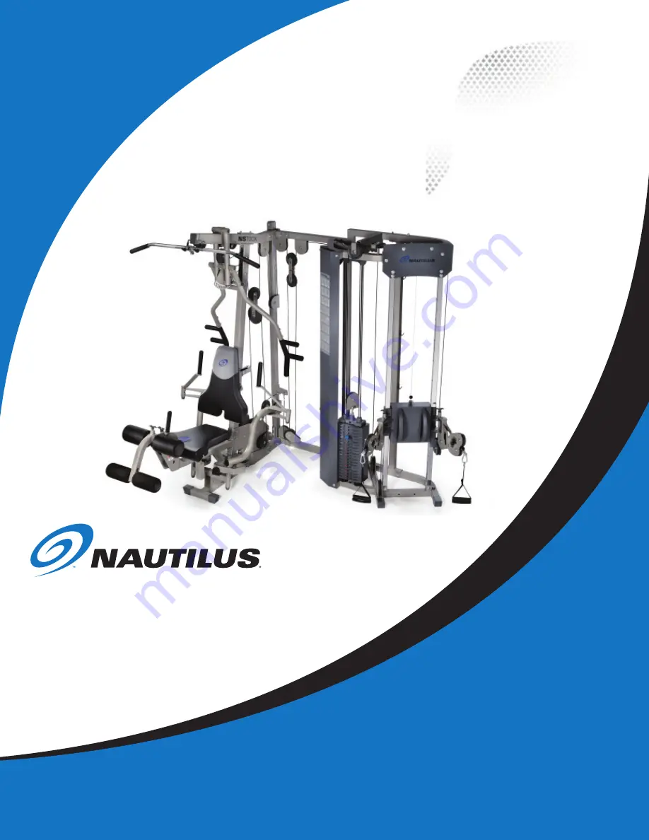
background image

Be Strong.

 Model: NS 

700

X

P/N: 001-7001 Rev A (09/28/2006)

 NS 

700X 

Assembly Manual

Summary of Contents for Be strong NS 700X

Page 1: ...Be Strong Model NS 700X P N 001 7001 Rev A 09 28 2006 NS 700X Assembly Manual...

Page 2: ...F CONTENTS Before You Assemble 3 Product Specifications 4 Product Features 4 Parts List Box Contents 5 Exploded View 6 Hardware and Tool List 7 Assembly Guide 8 Warranty Information 24 Contacting Naut...

Page 3: ...Principles Here are a few basic tips that will aid in the assembly of the Nautilus NS700X By using these principles you can simplify each process and save yourself extra time and effort 1 To make the...

Page 4: ...eight Adjustment Dual Floating Pulley System Exercise Placard NOTE All instructions in the manual are given with the orientation of sitting on the machine ready to exercise User Weight Capacity 300lbs...

Page 5: ...ng Bracket 2 63 Top Weight Pulley Housing 1 64 Connecting Bench Bracket 1 65 Bench Connecting Plate 1 66 Weight Plate 38 67 Plastic Cap 4 68 Snap Cap 2 Cable 69 1 Pull down Cable 263 75 L 1 70 2 High...

Page 6: ...pare the Bill of Materials to the box contents to insure that all parts are present before installation begins B Unpackage parts and place them near the final asssembled location to avoid moving the g...

Page 7: ...Nautilus NS700X Hardware and tools...

Page 8: ...ose to the gym s final position B Attach Rear Support Upright A and B 3 4 to Rear Base Frame 1 using the hardware shown Do not tighten hardware NOTE Rear Support Upright A 3 is the longer piece C Atta...

Page 9: ...o not tighten hardware B Attach Rear Upright 5 to Rear Base Frame 1 and Rear Top Frame 2 using Connecting Plate B 13 and the hardware shown Do not tighten hardware C Attach Leg Extension Frame 8 to Ma...

Page 10: ...onto Left Pec Fly Arm 19 paying close attention to the orientation shown above Attach the Left Pec Fly Arm 19 to the Pec Fly Mount 17 using the hardware shown Tighten hardware securely making sure th...

Page 11: ...4 Components Procedure A Attach Press Arm Support Assembly 22 to the Top Beam 6 using the Press Arm Support Shaft 26 Align shaft and tighten the 4 Set Screws 92 firmly B Remove Pop Pin from Press Arm...

Page 12: ...Seat Adjuster 31 in Leg Extension Frame 8 in the slot shown Install Pop Pin 30 using an adjustable wrench NOTE Pop Pin is threaded so that the seat can be locked into position D Attach Back Pad Tube...

Page 13: ...est fit for the user B Slide a Plastic Washer 40 followed by a Foam Roller 42 on the Roller Bar 39 Press the Roller End Cap 44 firmly into the Roller Bar 39 Repeat for the opposite side C Slide the Lo...

Page 14: ...re Carefully slide the Hi Low Pulley Adjuster 48 to the bottom adjustment hole Align the guide rods and snug the hardware but do not tighten C Attach the Power Spring Assembly 45 and Front Plate 46 to...

Page 15: ...een Weight Plates 66 and the Selector Rod Top Plate Assembly 52 53 on the Guide Rods 51 as shown Install Weight Plates 66 so that the selector pin hole faces for ward and is located on the bottom of t...

Page 16: ...n in detail A Tighten hardware securely Attach the Top Weight Pulley Housing 63 to the Selector Rod Top Weight Assembly 52 53 Do not tighten hardware D Loop Cable 2 70 over a 4 1 2 Pulley 58 and attac...

Page 17: ...the Front Upright 7 using the hardware shown Tighten hardware securely F Loop Cable 1 69 around a 4 1 2 Pulley 58 and attach the pulley to the bracket on the Top Beam 6 using the hardware shown Procee...

Page 18: ...18 NS700X Press Arm Assembly STEP 10...

Page 19: ...cket on the Rear Upright 5 using the hardware shown Proceed by looping the cable around a 4 1 2 pulley 58 and attaching the pulley to the bracket on the Rear Base Frame 1 using the hardware shown Tigh...

Page 20: ...Cam as shown in Detail A Tighten hardware securely C Draw Cable 3 71 around the left pulley in the Pec Fly Pulley Bracket 37 as shown Proceed by looping the cable around the pulley on the left side of...

Page 21: ...rew 3 8 x 1 2 L with thread lock 4 95 3 8 Flat Washer 4 112 Weight Stack decals 38 Step 13 Components Procedure Assembly STEP 13 A Attach the Shroud 59 to the gym using the hardware shown B Adhere the...

Page 22: ...Tensioning A Tighten the Cable System using a combination of five adjustment locations These locations are the Double Floating Pulley Brackets the Selector Rod Top Plate Assembly the Top Weight Pulle...

Page 23: ...Nut 4 Step 11 Components Procedure Assembly STEP 15 A Attach the Connecting Bench Bracket 64 to the Rear Base Frame 1 using the hardware shown Tighten hardware securely B Remove the hardware used on...

Page 24: ...due to use by persons who weigh more than 300 pounds Damage due to abuse misuse accident or acts of God such as floods Consequential or incidental damages Some states do not allow the exclusion or lim...

Page 25: ...ilus Inc World Headquarters 16400 S E Nautilus Drive Vancouver Washington USA 98683 Phone 800 NAUTILUS INTERNATIONAL CUSTOMER SERVICE INTERNATIONAL OFFICE Nautilus International S A Rue Jean Prouv 6 1...

Page 26: ...hts reserved Nautilus the Nautilus logo My Nautilus Heart Strong Changing the Game in Health and Fitness REACT ROC Remote Operation Control SuperSoft Hyperdrive Be Strong are either registered tradema...

Reviews: