Acquire an Image
A.
Launch Vision Builder AI.
B.
Expand the
Execution
Target
pull-down listbox,
and click
Select Network
Target
.
C.
Select the NI CVS-1450
device you configured,
and click
OK
.
D.
On the Vision Builder AI
Welcome screen, click
Configure Inspection
.
E. From the Acquire Images palette,
F. Click the Snap button to acquire a
click
Acquire Image (IEEE 1394)
.
single image, or click the Grab button
to acquire continuous images.
Once you have configured your acquisition, click
OK
to add the step. You can now add
inspection steps as described in the
NI Vision Builder for Automated Inspection: Configuration Help
.
4
Configure the NI CVS-1450 Device
Obtain an IP Address
A.
Launch Vision Builder AI.
B.
Expand the
Execution
Target
pull-down listbox
and click
Select Network
Target
.
C.
In the Select Remote
Target window,
click
192.168.10.12
to
highlight the row.
This IP address
is assigned to all
unconfigured NI
CVS-1450 devices.
Tip
To uniquely identify unconfigured NI CVS-1450 devices, connect and configure
one NI CVS-1450 device at a time.
D.
Click C
Co
on
nffiig
gu
urre
e to launch the Remote Target Configuration Wizard.
E.
In the Identification
window, enter a name
for the NI CVS-1450 device
in the N
Na
am
me
e field and a
description of the
NI CVS-1450 device in
the D
De
essc
crriip
pttiio
on
n field.
Note
Device names
are limited to 15
characters with no
spaces or special
characters. The first
and last letters must
be alphanumeric.
F.
Click
Next
.
G.
If the network is
configured to issue IP
addresses using DHCP,
select
Obtain IP Address
from DHCP Server
.
Otherwise, set the IP
address manually by
selecting
Edit IP Settings
,
Suggest Values
, and
OK
.
H.
Click
Next
.
Download Software to the NI CVS-1450 Device
I.
Select the
Update Target
Software
checkbox.
J.
Click
OK
to begin
configuring the IP address
and downloading software
onto the NI CVS-1450
device. This initial
installation process
takes several minutes.
3
Connect the Hardware
Caution
Before installing NI CVS-1450 Series hardware, refer to the safety
information in the
NI CVS-1450 Series User Manual
.
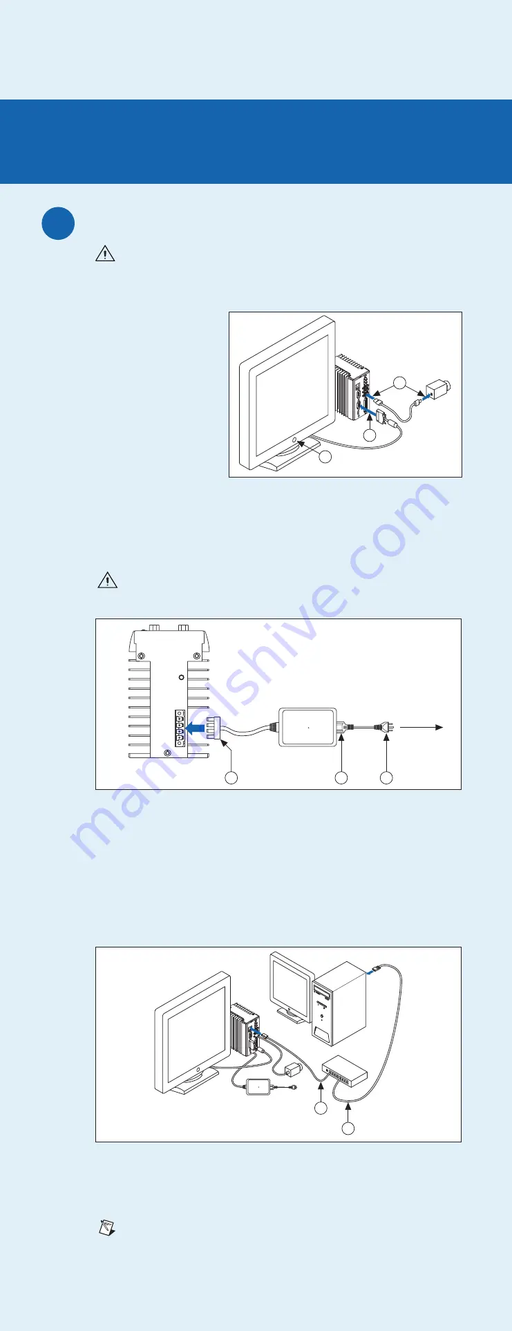
Connect the Camera and Monitor to the NI CVS-1450 Device
A.
Connect the VGA cable
from the monitor to
the VGA port on the
NI CVS-1450 device.
B.
Plug the IEEE 1394
cable into one of the
IEEE 1394 ports on the
NI CVS-1450 device.
Plug the other end of
the cable into the IEEE
1394 port of the camera.
C.
Plug in and power on
the monitor.
Wire Power to the NI CVS-1450 Device
This section explains how to connect the power supply (part number 778794-01)
to the NI CVS-1450 device. For instructions on how to connect a separate main supply,
refer to the
NI CVS-1450 Series User Manual
.
Caution
Do
not
connect the NI CVS-1450 device to a power source other than
24 VDC +10%. Refer to the
NI CVS-1450 Series User Manual
for information about
power requirements.
D.
Plug the 4-position connector from the power supply into the power receptacle
on the NI CVS-1450 device.
E.
Plug the power cord into the power supply.
F.
Plug the power cord into an outlet.
Once connected, the NI CVS-1450 device runs a startup program that acquires images and
displays them on the monitor. These images verify that the hardware is properly connected.
Connect the NI CVS-1450 Device to the Development Computer
Verify that the development computer is connected to the network and powered on.
G.
Using a standard CAT 5 Ethernet cable (part number 189174), connect from the
network port to the Ethernet port on the NI CVS-1450 device.
H.
Using a standard CAT 5 Ethernet cable, connect from the network port to the
Ethernet port on the development computer.
Note
If you are not connecting through a network, use a crossover cable
(part number 187375) to connect the NI CVS-1450 device to the development
computer.
G
H
F
To Outlet
E
D
1
QUICK START GUIDE
NI CVS-1450 Series
Compact Vision System
This document describes how to set up and acquire an image using the NI CVS-1450 Series
compact vision system with NI Vision Builder for Automated Inspection or the LabVIEW Real-Time
Module and the NI Vision Development Module. Use these instructions to verify that hardware
and software are properly installed, to configure an IP address for the CVS-1450 device, and to
acquire an image.
Note
These instructions are intended for
basic
installation and configuration.
Refer to the
NI CVS-1450 Series User Manual
and the application software
documentation for detailed installation and configuration instructions.
National Instruments, NI, ni.com, and LabVIEW are trademarks of National Instruments Corporation.
Refer to the
Terms of Use section on
ni.com/legal
for more information about National
Instruments trademarks. Other product and company names mentioned herein are trademarks or
trade names of their respective companies. For patents covering National Instruments products,
refer to the appropriate location:
Help»Patents
in your software, the
patents.txt
file on your CD,
or
ni.com/patents
.
© 2003–2006 National Instruments Corporation. All rights reserved.
Refer to the yellow side of this document if you are using the
LabVIEW Real-Time Module with the NI Vision Development Module
Refer to the blue side of this document if you are using
Vision Builder for Automated Inspection
Install the Software
Note
You must install Vision Builder for Automated Inspection (Vision Builder AI)
before
installing the NI-IMAQ for IEEE 1394 Cameras driver software.
Install Vision Builder AI and NI-IMAQ for IEEE 1394 Cameras
A.
Insert the Vision Builder AI CD. When the installation splash screen appears, click
Install Vision Builder for Automated Inspection
and follow the setup instructions.
Install NI-IMAQ for IEEE 1394 Cameras
B.
When prompted, insert the NI Vision Acquisition Software CD.
C.
In the Features tree, select N
NII--IIM
MA
AQ
Q ffo
orr IIE
EE
EE
E 11339944 C
Ca
am
me
erra
ass and N
NII--IIM
MA
AQ
Q ffo
orr IIE
EE
EE
E 11339944
H
Ha
arrd
dw
wa
arre
e S
Su
up
pp
po
orrtt.
D.
Click N
Ne
exxtt.
E.
Follow the installer prompts to complete the installation.
2
QUICK START GUIDE
NI CVS-1450 Series Compact Vision System
Vision Builder for
Automated Inspection
A
C
B
373609B-01
Mar06