De Luxe 311-BBS, Owner'S Manual
Introducing the De Luxe 311-BBS, a state-of-the-art device that comes with an Owner's Manual, providing comprehensive instructions for hassle-free operation. Experience the convenience of downloading this manual for free from manualshive.com, ensuring a seamless user experience. Get to know this exceptional product and maximize its potential with ease!
Share
Download


Reviews:
No comments
Related manuals for 311-BBS

EXPRESSCARD 1000
Brand: Magtek Pages: 37

OF5700
Brand: Oki Pages: 16

1118 Series
Brand: U.S. BLIND STITCH Pages: 32

BR 40/10 C Classic
Brand: Kärcher Pages: 196

Jem Platinum 720
Brand: Janome Pages: 41

OKIFAX 4550
Brand: Oki Pages: 128
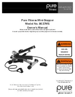
8637MS
Brand: Pure Fitness Pages: 12

713564
Brand: Schwamborn Pages: 50

GBC StreamPunch Ultra
Brand: ACCO Brands Pages: 92

FOG1500MULTI
Brand: afx light Pages: 19

ULTRA-STITCH SM-1100
Brand: Mueller Pages: 28

EaglePower SILVER Series
Brand: IPC Pages: 8

Sweepmaster B1500 RH
Brand: HAKO Pages: 70

Adgressor BR 1050CS
Brand: Nilfisk-Advance Pages: 82

Modular TL2900
Brand: GBC Pages: 38

LK-980 Series
Brand: JUKI Pages: 52

SE200-M SERIES
Brand: Suzuki Pages: 29

AW-7020-8000
Brand: Mi-T-M Pages: 20


