Nagasoft NSCaster X1, User Manual
The Nagasoft NSCaster X1 User Manual is your comprehensive guide to unlocking the full potential of this groundbreaking device. Easily download this manual for free from our website and gain valuable insights on setup, functionality, troubleshooting, and more. Get the most out of your NSCaster X1, effortlessly!
Share
Download


Reviews:
No comments
Related manuals for NSCaster X1

Slate
Brand: Bamboo Pages: 80
Tablet
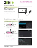
Brand: Zeki Pages: 2
Tablet
Brand: Yarvik Pages: 20

102.127
Brand: Fenton Pages: 20

OliPadSmart
Brand: Olivetti Pages: 28

DreamTab DMTAB-NV08B
Brand: NABI Pages: 9

Viega
Brand: VIA Technologies Pages: 34

TT-B300BT
Brand: Essentielb Pages: 23

DigiMemo A501
Brand: Acecad Pages: 19
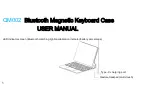
QM002
Brand: KEXIN Pages: 9

DT301A
Brand: DT Research Pages: 10

Artisul D13
Brand: UC Logic Pages: 46

LPT-200AR
Brand: LG CNS Pages: 52

2187
Brand: ETS-Lindgren Pages: 11

BLACKBOX RECORDER
Brand: JoeCo Pages: 52

5706751040115
Brand: Denver Pages: 26

10248
Brand: Denver Pages: 17

Ultimate 11i WIN
Brand: Lark Pages: 58


