background image


User’s Guide

 (Ver. 4.0) 


Analog DVR: N-0441U, N-0840U, N-1640L, N-0440MH, N-0840MH, N-1640MH, ND-1640S   


HD-SDI DVR: HD-0405M, HD-0810M, HD-1620S, HD-0410S, CM-1040S 

High Definition H.264 Digital Video Recorder 
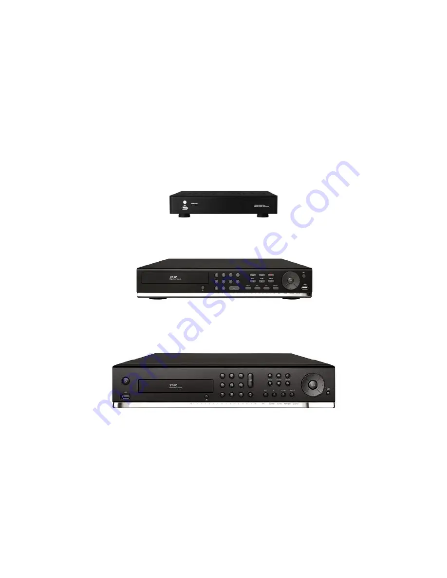


[N-0441U, N-0841U] 


[HD-0405M, HD-0810M, N-0440MH, N-0840MH, N-1640MH, ND-0823M, ND-1643M] 


[HD-1620S, CM-1040S, HD-0410S, ND-1640S] 


About This User’s Guide 

Before operating the unit, please read this user’s guide thoroughly and retain it for future reference. 

Summary of Contents for CM-1040S

Page 1: ...810M HD 1620S HD 0410S CM 1040S High Definition H 264 Digital Video Recorder N 0441U N 0841U HD 0405M HD 0810M N 0440MH N 0840MH N 1640MH ND 0823M ND 1643M HD 1620S CM 1040S HD 0410S ND 1640S About This User s Guide Before operating the unit please read this user s guide thoroughly and retain it for future reference ...

Page 2: ...wer supply 9 Lighting For added protection for this product during a storm or when it is left unattended and unused for long periods of time unplug it from the wall outlet This will prevent damage to the product due to lighting and power line surges 10 Object and Liquid Never insert foreign objects into the DVR as it may touch dangerous voltage points or short out parts that could result in a fire...

Page 3: ...me The product may become warm after long periods of use Locating Place the unit on a level surface Do not place the unit on a shaky or unstable surface such as a wobbling table or an inclined stand If the unit is placed next to a TV radio or VCR the playback picture may become poor and the sound may be distorted If this happens place the unit away from the TV radio or VCR Maintenance This DVR is ...

Page 4: ...ation 17 2 2 Hard Drive Installation 18 2 4 Storage Estimation 19 2 5 Booting the DVR and Basic Time Setting 19 2 6 Setting Daylight Saving Time 20 2 7 Setting NTP Network Time Protocol 21 3 Setting up the DVR 24 3 1 Setup Main screen and Menu Tree 24 3 2 Setup Display Mode 28 3 3 Setup Record Mode 30 3 3 1 Recording Schedules 31 3 4 Setup Device Mode 33 3 4 1 ALARM OUT 34 3 4 2 SPOT OUT Setup 34 ...

Page 5: ...1 PC Requirements 61 7 2 Installing the Network Viewer 62 7 3 Live Monitoring Mode and Functions 63 7 4 Bi directional Audio 65 7 5 Remote Search Mode and Functions 65 7 6 PC System Configuration 69 8 Multi Sites Network Viewer 72 8 1 Overview 72 8 2 Minimum PC Requirements 72 8 3 Installation of the Program 72 8 4 Live Window 74 8 4 1 Main User Interface 74 8 4 2 Control Buttons 74 8 5 Search and...

Page 6: ...talling the Viewer 99 11 2 iUMS for Android 99 11 2 1 Live 99 11 2 2 PTZ Control 100 11 3 iUMS for iPhone 101 11 3 1 Live 101 11 3 2 PTZ Control 101 11 3 3 Playback 102 APPENDIX How to Connect the Network 103 A How to set the IP address of the DVR and open TCP port of the router 103 B How to access DVR from a Remote PC 106 LAN Connection Using a Switching Hub 106 Internet Connection Using DDNS 108...

Page 7: ...ied below DVR Set Client Software CD User Guide Remote Control Battery1 5V Mouse HDD Mounting Bracket Screw SATA Cable SATA Power Cable HDD DVD RW Mounting Screw HDD DVD RW Mounting Bracket Power Cable Power Adapter 1 EA Power Cable 110V or 220V 1 EA For HD 1620S CM 1040S HD 0410S ND 1640S only ...

Page 8: ...g mode detection zone Various network access Network client SW web viewer smart phone APP and CMS Remote setup and remote upgrade Remote access via PC MAC or smart phones Recording by schedule continuous alarm motion or continuous Free DDNS server Bandwidth control E mail event notification NTP Network Time Protocol Watermark Synchronized audio Bi directional audio Time stamp over backup data Easy...

Page 9: ...re triggered or motion is detected D NETWORK Indicates that a network client is connected E BACKUP Indicates that a USB or DVD RW device contains stored data F POWER Indicating that the system is powered on Front Panel Buttons NO Name Description 1 Channel keys For channel 10 press the 0 key For channel 11 press the 10 and 1 key For channel 16 press the 10 and 6 key 2 In playback mode press to rew...

Page 10: ...e left or to change the values in Setup mode It is also used as the number 4 when entering password 16 UP Press to move up the menu in Setup mode It is also used as the number 1 when entering password 17 RIGHT Press to move right or to change the values in Setup mode It is also used as the number 2 when entering password 18 DOWN Press to move down the menu in Setup mode It is also used as the numb...

Page 11: ...re triggered or motion is detected E NETWORK Indicating that when Network client connects through the network F BACKUP Indicating that USB or DVD RW storage device is stored images or video Front Panel Buttons NO Name Description 1 POWER ON OFF 2 Channel keys For channel 10 press the 0 key For channel 11 press the 10 and 1 key For channel 16 press the 10 and 6 key 3 Press to rewind the footage in ...

Page 12: ...ve left or to change the values in Setup mode It is also used as the number 4 when entering password 14 UP Press to move up the menu in Setup mode It is also used as the number 1 when entering password 15 RIGHT Press to move right or to change the values in Setup mode It is also used as the number 2 when entering password 16 DOWN Press to move down the menu in Setup mode It is also used as the num...

Page 13: ...anel 1 2 1 N 0441U N 0841U N 1640L 1 Video Input 2 CVBS Video Output 3 VGA Output 4 Audio Input 5 Audio Output 6 Network RS 45 Ethernet Port 7 USB Port 8 DC12V Power Input 1 2 2 N 0440MH N 0840MH N 1640MH ND 0823M ND 1643M ...

Page 14: ...SB Port 10 RS 485 PTZ Camera control terminal 11 DC12V Power Input 1 2 3 ND 1640S 1 Video Input Loop Out 2 Video Output 3 Audio Input 4 RS 485 PTZ Camera control terminal Sensor In terminal 5 VGA Output 6 HDMI Output 7 USB Port 8 RS 232 Terminal For testing purposes 9 Network RS 45 Ethernet Port 10 eSATA Port 11 RS 485 Termination 12 DC12V Power Input 1 2 4 HD 0405M HD 0810M HD1620S ...

Page 15: ... Port 10 RS 485 PTZ Camera control terminal 11 DC12V Power Input 10 eSATA Port RS 485 11 DC12V Power Input 1 Video Input Loop Out 2 Video Output 3 Audio Input 4 RS 232 Terminal For testing purposes 5 VGA Output 6 HDMI Output 7 USB Port 8 RS 485 PTZ Camera control terminal 9 Network RS 45 Ethernet Port 10 eSATA Port 11 RS 485 Termination 12 Sensor In terminal 13 DC12V Power Input ...

Page 16: ...2x and 4x speed during playback PLAY PAUSE To play or to pause the footage in playback mode FF To fast forward the footage at 1x 2x and 4x speeds during playback Control button Press to move the menu items or select channel SETUP To launch SETUP menu SEARCH To go to the search menu ESC During setting To return to previous menu screen During playback To exit from playback System Lock To lock a syst...

Page 17: ...lation 1 Remove the screws and the top cover as specified below 2 Install the DVD RW mounting bracket to the DVD RW by using the mounting bracket screws as specified below 3 Connect the DVD RW Data Power Cable to both the DVD RW and main board ...

Page 18: ...lling bracket and screws onto the HDD 2 Install the mounting bracket on the HDD 3 Installation HDD and Bracket onto base case Inside 4 Installation HDD and Bracket onto base case Outside 5 Connect the Data Power cable to the HDD 6 Installed HDD and DVD RW ...

Page 19: ...evel 5 H Level 4 Level 3 Level 2 Level 1 L Capacity day s hour s day s hour s day s hour s day s hour s day s hour s 250GB 0 22 1 3 1 12 1 20 2 6 320GB 1 5 1 12 2 0 2 9 3 23 500GB 1 22 2 10 3 5 3 20 4 18 1TB 4 23 5 23 6 14 7 21 9 18 1 5TB 6 0 7 12 10 22 11 21 14 18 2TB 8 1 10 1 13 7 15 22 19 18 2 5 Booting the DVR and Basic Time Setting 1 During the first start up the following message will be dis...

Page 20: ... Day Light Saving Time and be synchronized NTP Network Time Protocol Take next steps 1 Click a mouse right button or SETUP button on the front panel of DVR to enter the SETUP mode The default Password is 1111 2 Go to SETUP SYSTEM SET DATE TIME 3 Select DAYLIGHT SAVING ...

Page 21: ...A USA GMT 8 00 for Standard time GMT 7 00 for Daylight time Mountain Time Zone Denver CO USA GMT 6 00 for Standard time GMT 5 00 for Daylight time Central Time Zone Chicago IL USA GMT 7 00 for Standard time GMT 6 00 for Daylight time Eastern Time Zone Newyork NY USA GMT 5 00 for Standard time GMT 4 00 for Daylight time State Standard Time Daylight Saving Time AL Alabama GMT 6 GMT 5 AK Alaska GMT 9...

Page 22: ... 4 IN Indiana SW NW GMT 6 GMT 5 IA Iowa GMT 6 GMT 5 KS Kansas GMT 6 GMT 5 KS Kansas W GMT 7 GMT 6 KY Kentucky E GMT 5 GMT 4 KY Kentucky W GMT 6 GMT 5 LA Louisiana GMT 6 GMT 5 ME Maine GMT 5 GMT 4 MD Maryland GMT 5 GMT 4 MA Massachusetts GMT 5 GMT 4 MI Michigan GMT 5 GMT 4 MI Michigan W GMT 6 GMT 5 MN Minnesota GMT 6 GMT 5 MS Mississippi GMT 6 GMT 5 MO Missouri GMT 6 GMT 5 MT Montana GMT 7 GMT 6 NE...

Page 23: ...akota E GMT 6 GMT 5 SD South Dakota W GMT 7 GMT 6 TN Tennessee E GMT 5 GMT 4 TN Tennessee W GMT 6 GMT 5 TX Texas GMT 6 GMT 5 TX Texas W GMT 7 GMT 6 UT Utah GMT 7 GMT 6 VT Vermont GMT 5 GMT 4 VA Virginia GMT 5 GMT 4 WA Washington GMT 8 GMT 7 WV West Virginia GMT 5 GMT 4 WI Wisconsin GMT 6 GMT 5 WY Wyoming GMT 7 GMT 6 NOTE If you want the unit to automatically synchronize the local time the Time Zon...

Page 24: ...m the submenu or press the setup button on the front panel or the remote control Figure 3 1 1 Setup Menu Tree When the DVR prompts the LOG IN window enter the PASSWORD using the virtual keyboard or the front panel or the remote control The factory default password is 1111 It is highly recommended to assign a new password to protect the system User can assign a new password in SECURITY setup menu ...

Page 25: ...CONTRAST SEQUENCE SEQUENCE DWELL TIME CHANNEL NAME COVERT BRIGHTNESS CONTRAST HUE SATURATION VIDEO OUTPUT RECORD CHANNEL RESOLUTION FRAME RATE QUALITY RECORDING SENSOR RECORDING PRE RECORD POST EVENT RECORD AUDIO SCHEDULE DEVICE ...

Page 26: ...UT 2 CHANNEL MOTION ZONE MOTION SENSITIVITY KEY TONE REMOTE CONTROLLER ID SENSOR TYPE STORAGE OVERWRITE DISK FORMAT DISK INFO RECORDING LIMIT S M A R T SYSTEM DVR ID DESCRIPTION LANGUAGE DATE FORMAT SET DATE TIME DAYLIGHT SAVING SET DATE TIME CLIENT ACCESS NTP SEND EMAIL SECURITY USER AUTHENTICATION ADMIN NETWORK USER1 USER2 USER3 USER PASSOWRD ...

Page 27: ... PORT NETWORK TYPE DHCP LAN DDNS NETWORK STREAM CONFIG SAVE SETUP TO A USB LOAD SETUP FROM A USB LOAD DEFAULT LOAD FACTORY DEFAULT SOFTWARE UPGRADE QUICK SETUP USE QUICK SETUP INPUT DESIRED DAYS CUSTOMER SETTINGS RESOLUTION FRAME RATE QUALITY RECORDING DAYS TO RECORD ...

Page 28: ...SD 0 100 SEQUENCE Enable disable sequential display of video in full screen mode SEQ DWELL TIME Set the dwell time of each quad or 9 channels display in sequential display mode 3 60seconds CHANNEL Select a channel for applying the following settings using the mouse or control button on the remote control Press the right square button to change the setting value of all channels at once Press SEL bu...

Page 29: ...splay of the specified video channel in live display mode BRIGHTNESS Change the brightness value of the specified channel 0 100 CONTRAST Change the contrast value of the specified channel 0 100 HUE Change the hue value of the specified channel 0 100 SATURATION Change the saturation value of the specified channel 0 100 VIDEO OUTPUT HDMI VGA Allows user to set monitor output resolution from 720p 50H...

Page 30: ...are button to change the setting value of all channels at once Once you the value has been changed select OK to confirm the changes RESOLUTION FRAME RATE QUALITY RECORDING PRE RECORD and POST EVENT RECORD RESOLUTION Analog DVR Select either CIF Half D1 and D1 using the mouse or the control button on the remote control HD SDI DVR Select either 640 x 360 1280 x 720 1920 x 1080 using the mouse or the...

Page 31: ...RD menu Navigate through the menu items using the mouse or the control button on the remote control Channel Select the specific channel Setup Set up using the left button of the mouse to section under the specific day and time It can set the all section under the specific day or time at a time when pressing the specific day or time It is also possible to set up recording modes of various type usin...

Page 32: ...32 P a g e Figure 3 3 2 Schedule Recording Setup Screen ...

Page 33: ...monitoring It supports 2 spot outs CHANNEL Select specified channel for motion zone setup MOTION ZONE Select either Full Zone or Partial Zone for motion sensing MOTION SENSITIVITY Set the motion sensitivity for the specified channel Control the motion sensitivity from 1 to 9 KEY TONE Enable disable key tone REMOTE CONTROL ID Select an ID of remote control 1 Select ID number 2 Press the same number...

Page 34: ...on The options are OFF ALL HDD ERROR and VIDEO LOSS 3 4 2 SPOT OUT Setup Figure 3 4 3 SPOT OUT Setup Screen Table 3 4 3 Menu item in SPOT OUT Setup Screen Item Description SPOT ON EVENT Enable Disable display of the channel when an event is active SPOT EVENT DWELL TIME Set the dwell time for the display of the event activated channel 1 10sec SEQUENCE Enable disable sequential display of spot chann...

Page 35: ...onnect them directly to the RS 485 port If the camera is controlled with RS 232C use a RS 485 to RS 232C signal converter On the PTZ control setup screen you can select or set the protocol type of the camera that is the same as the one installed on the site If the camera has a specific camera ID select the camera ID using the mouse or the control button of the remote control The following options ...

Page 36: ... MOTION SENSITIVITY FULL ZONE The motion sensor is active on the whole screen PARTIAL ZONE The motion sensor is active in the set detection frame Select the motion detection position using the mouse or the control button on the remote control Then left click on the mouse or left click and drag the mouse pointer to select or deselect the area Highlighted area indicates the partial motion detection ...

Page 37: ...ue recording and overwrite the oldest existing recorded data once the hard drive is full When disabled recording will stop once the hard drive is full DISK FORMAT You will have an option YES or NO for the hard drive format Caution We recommend that you archive any data that you may need in the future before you format the hard drive DISK INFO Hard drive information RECORDING LIMIT Enable disable r...

Page 38: ...ress OK to apply the DVR ID DESCRIPTION Press the button to view the system information Hardware version Software version Storage size IP address MAC address and DDNS status and Port Forward Status LANGUAGE Select the display language using the mouse or the control button on the remote control Once a language is selected the display language changes DATE FORMAT Select the date display format using...

Page 39: ...ing value using the control button and press the ESC button to return to SET DATE TIME setup menu CAUTION Do not set the start time to 23 00 for DLS DLS can t be applied if the date of BEGIN and END is the same CLIENT ACCESS Enable Disable remote access through network client software NTP NTP is an abbreviation for Network Time Protocol which is for synchronizing the time of the computer systems o...

Page 40: ...riggered S M A R T Allows the user to set S M A R T NOTIFICATION ON or OFF MAIL PORT Allows the user to set E MAIL PORT SECURE OPTION NONE SSL TLS Allows the user to select E MAIL SECURE OPTION MAIL TO Enter the appropriate email address to enable sending e mail reports using a virtual keyboard MAIL SERVER Enter the appropriate mail server information to enable sending daily e mail reports using a...

Page 41: ...Setup Screen Table 3 7 1 Menu Items in PASSWRORD Setup Screen Item Description USER AUTHENTICATION Admin only can access to the menu PASSWORD CHECK Select either V or nothing for the functions such as Setup Playback PB PTZ Record OFF R OFF and Network Selected Checkbox The DVR will ask for a password when the given function is selected for all users Blank Checkbox The DVR will not ask for a passwo...

Page 42: ...t OK Then the message PASSWORD CHANGED is displayed The factory default password is 1111 PLAYBACK AUTHORITY Allows specific users AUTHORITY OF PLAYBACK per CHANNEL When the user set this function the login window will appear Then the user can select one of user types ADMIN USER1 USER2 USER3 using the mouse or the control button on the remote control The user can select a password using the mouse o...

Page 43: ...streaming NETWORK PORT 1 WEB PORT Web Sever Port number Default 80 NETWORK TYPE Select a type of network connection Options are STATIC DHCP DHCP DVR will automatically retrieve an IP address from the network LAN Network information must be manually configured DHCP DVR will automatically retrieve an IP address from the network LAN IP Register IP address that is assigned for the DVR Gateway Register...

Page 44: ...from 5 to 60 minutes To connect to a network with a domain name the user must register a MAC address and serial number of the DVR and create a unique domain name on http www ddnscenter com Select ddnscenter com from the three DDNS servers If you select other DDNS server the DVR cannot connect to the DDNS properly Please refer to Appendix How to connect network section for the detail of the registr...

Page 45: ...me LAN the TCP port does not have to be changed 3 8 3 Network Stream User can set the frame rate and the bit rate for a network stream for a specific channel Note The network streaming is possible to set up to the recording frame rate of the channel Figure 3 8 4 Network Setup Screen Network Stream Network Access Beyond a Router In order to access the DVR remotely beyond a router firewall the user ...

Page 46: ...onfiguration Setup Screen Table 3 9 1 Configuration Setup Item Description SAVE SETUP TO A USB User can save the current configuration Setting values of the DVR to the USB flash drive Plug in the USB flash on the front panel and press the button to start the saving process LOAD SETUP FROM A USB User can upload the configuration of the DVR to another DVR using the USB Flash drive Plug in the USB fl...

Page 47: ... format DLS settings Network settings HDD overwrite Limit recording HDD serial number and HDD ERROR time will not be included LOAD FACTORY DEFAULT Press the button to reset the system to the factory default settings SOFTWARE UPGRADE Upgrade softeware to the latest version After connecting USB flash drive to USB port on the DVR click SEARCH It will automatically find the upgrade file ...

Page 48: ...g to channel Figure 3 10 1 Quick Setup Screen Table 3 10 1 Quick Setup Item Description USE QUICK SETUP Select the Checkbox to use the Quick Setup When user inputs the DESIRED DAYS to record the system displays a recommended resolution frame rate quality and recording type after calculating the capacity of the installed HDD At that time the priority is followed by the order of the items resolution...

Page 49: ...ewing Screen Table 4 1 1 Status Indicator Icons in Live Viewing Screen Icon Description Power On Off button Lock Unlock Setup button Setup button Click this button to go to a setup menu Audio button Click this button to set an audio reception type Audio Mute 1 channel or 4 channels To set just 1 channel select a specific channel on the live screen at first Search button Click this button to enter ...

Page 50: ...ress To set the Manual recording mode press the Record button on the front panel Motion alarm recording in progress Sensor recording in progress Indicates that the lock is set Audio mute To set audio mute press the Audio button on the front panel Single audio display To set audio single for highlighted channel only press the Audio button on the front panel To mix audio display press the Audio butt...

Page 51: ...GO TO FIRST TIME GO TO LAST TIME GO TO SPECIFIC TIME ARCHIVE and LOG on the screen How to Search Data On the Time Line Using the Mouse or Front Key Button 1 hour moving 1 hour time bar Mouse F REW and F ADV button Front Key 5 minute moving 12 00 00 Mouse control button Front Key There are 7 ways of search menu such as TIMELINE EVENT GO TO FIRST TIME GO TO LAST TIME GO TO SPECIFIC TIME ARCHIVE and ...

Page 52: ...meline menu is selected the user can see a calendar which has the recorded data Select a specific date and time Use a drag and drop function of the mouse control User can select a specific minutes using a button in the above red box Press the PLAY button after selecting the specific time Press the PREV to return to the SEARCH window ...

Page 53: ...er selecting the specific data User can find a data of the specific channel and event using a button in the above red box Press the PREV to return to the SEARCH window 4 2 3 Go To First Time You can access from the oldest recorded data on the DVR hard drive by selecting GO TO FIRST TIME on the SEARCH window Press the PREV to return to the SEARCH window 4 2 4 Go To Last Time You can access from the...

Page 54: ...r setting If there are not video data in the set date and time No Data Exist message displays 4 2 6 Archive Search The ARCHIVE Search window is used to find previously stored video or images Figure 4 2 4 Archive Search Screen When the Archive menu is selected the user can see a calendar which has recording data Select a specific date and then the archived data will be displayed Press the Display b...

Page 55: ...ARCH window Figure 4 2 5 Log Search Screen When the Log menu is selected the user can see a calendar which has recording data Select a specific date and press NEXT button and then the log data will be displayed Press the SAVE button to save the data and then the data is saved as a text file format ...

Page 56: ...tion Return to the previous menu screen search window or exit from the Menu Press to rewind the footage at 1x 2x and 4x speeds Reverse playback speed is shown as 1x normal 2x 2 times normal and 4x 4 times normal at the bottom right of the screen Jump Step backward The playback position moves 60 seconds backward II Press to play or pause recorded video Jump Step forward Playback position moves 60 s...

Page 57: ...ntrol keys are Right Left UP Down Select Far REW KEY and Near FF KEY Press the ESC button to return to the main menu Press the PTZ button to escape from the OSD menu AUTOSCAN Press the right key on the control button to start auto scan Press the left key on the control button to stop auto scan PRESET Select the PRESET and press the left key on the control button Then number input window will appea...

Page 58: ... of the USB flash drive has to be FAT32 6 2 Video Backup onto USB Flash Drive Video can be captured and archived onto the USB flash drive or a hard drive while playing back the recorded video In playback mode press the BACKUP button to launch the archiving function 1 When you press BACKUP button the DVR will ask whether to archive a Still Image or Video Clip 2 If the user selects VIDEO CLIP the DV...

Page 59: ...l 2 Once you have selected the date press the NEXT button to open the list of stored data 3 Use the mouse or the control button on the remote control to scroll through the archive list 4 Select a list of stored events that happened previous or after the current selection 5 Once the desired event has been selected press the DISPLAY button to view the still image or the first frame of the selected v...

Page 60: ...AVI format video NSF format H 264 format video can be played back using the player the HD player that the DVR copies on USB flash drive with video This format is only available when the user selects a huge backup Three files are copied on USB flash drive H 264 file H 264 format video file INDEX file Title file of date and time HD PLAYER Exclusive video viewer ...

Page 61: ...ents Minimum PC Requirements Recommended PC requirements CPU Intel PentiumⅣ 2Ghz Memory 512MB VGA 128MB Resolution 1024x768 Disk Space 1GB OS Windows 2000 XP Professional XP Home Vista 7 NOTE Not all versions of Vista and 7 are supported Network 10 100Base T Others Direct X 8 1 or Higher CPU Intel Core 2 Duo 1 8Ghz or higher Memory 1GB DDR2 or higher VGA 512MB or higher Resolution 1024x768 Disk Sp...

Page 62: ... CD in the CD drive and double click UMSClient XXXX exe 2 Select a destination folder and click Next 3 Select the program folder and click Next 4 The setup status screen is displayed 5 After the installation is completed UMS Client icon displays on the desktop screen ...

Page 63: ...ent date and time CONNECT DISCONNECT Connect disconnect network connection SEARCH Switches the live mode to search mode DISPLAY MODE Select a channel and screen display mode PAN TILT ZOOM FOCUS Control the PAN TILT ZOOM FOCUS features on the remote camera CAPTURE Capture a still image from the live screen ...

Page 64: ...ransferred frames and network bandwidth AUDIO Adjust the volume The audio can be turned on or off by clicking the audio icon LOG WINDOW Shows the even log date and time Operations of the display mode of the main screen Single channel display Click the one of channel button or double click the channel screen QUAD screen display Click the QUAD button to switch to quad screen display Full screen disp...

Page 65: ...d 2 Click the CAPTURE button Then the IMAGE CAPTURE dialog is displayed 3 Set the SAVE PATH FILE NAME and FILE FORMAT and click the OK button to save the captured still image 7 4 Bi directional Audio The UMS Client allows for bi directional audio between the client and the DVR unit The DVR must have an audio input connected and the PC must have an audio output 7 5 Remote Search Mode and Functions ...

Page 66: ...in a light blue and the selected date in dark blue TIMELINE BAR The timeline shows recorded data in dark blue on the bar PLAYBACK BUTTON The playback buttons DISPLAY MODE Select a channel and screen display mode Searching and playing video in the remote DVR Video recorded in the remote DVR or Video recorded on the PC can be searched and played back 1 Connect to the remote DVR and press the SEARCH ...

Page 67: ...ote DVR can be backed up on the PC HDD as an AVI format or NSF format 1 Connect to the remote DVR and play the video recorded in the remote DVR 2 Drag the marker on the timeline scale and press the MARK IN button to mark the video backup starting point 3 Drag the marker on the timeline scale and press the MARK OUT button to mark the video backup ending point Then the selected marked time to backup...

Page 68: ... the backup process Select Channels Select channels to backup Start Time Stop Time Backup time can be changed File Path Shows the folder that the backup file is recorded File Format Select backup file format NOTE File format selection may not be available depending on the firmware version software version and the DVR model ...

Page 69: ... will need to enter the password Save Path Specify the location to record for backup and still image capture Automatic reconnection If a user selects this function the client S W will automatically try to connect to the previously connected IP address if the network connection is lost Display network statistics If a user selects this function the client S W will display network status Bit rate and...

Page 70: ...d and removed Setting Event Set the record path and the size of local disk space for the log files LOG Select to save event log into log file ICON Select to display the event on live video EVENT LIST Select to show the event in the Event List window of live mode ...

Page 71: ...ch and check the recorded log data Setting Record Set the recording conditions and select channels to record Select the local disk to use and the amount of disk space you want to allow the program to use for recording ...

Page 72: ...n site user may make bi directional audio communication over the network 8 2 Minimum PC Requirements Before installing the program check the PC specifications The DVR remote software may not perform correctly if the PC does not meet the minimum requirements 8 3 Installation of the Program 1 Insert the provided CD in the CD drive and double click UMSMultiClient XXXX exe CPU Intel PentiumⅣ 2Ghz Memo...

Page 73: ...ct a destination folder and click Next 3 Select the program folder and click Next 4 The installation status screen is displayed 5 After the installation is completed UMS Multi Client icon displays on the desktop screen ...

Page 74: ...n the local PC REMOTE PLAYBACK Click this icon to run a playback window to search and play videos that are recorded in the remote DVR SITE MANAGEMENT THUMBNAIL REFRESH Click this icon to refresh and renew thumbnail image of the connected sites SITE ADDITION Click this icon to open Site Addition window SITE DELETE Click this icon to delete site from the index window after disconnect a site NET FIND...

Page 75: ... set in setup menu AUDIO Use the volume control bar to set the audio level MIC Use the micro phone volume control bar to set the micro phone level User can control PAN TILT ZOON FOCUS PAN left right TILT up down ZOOM in out FOCUS in out CHANNEL SPLIT To select the numbers of display channel channels Single quad 9 channels and 16 channels of highlighted site DVR SITE SPLIT To select the numbers of ...

Page 76: ...s that are recorded in the local PC REMOTE PLAYBACK Click this icon to run a playback window to search and play videos that are recorded in the remote DVR Directory window shows site sites that are pre registered CONNECT Click this icon to connect the selected site sites DISCONNECT Click this icon to disconnect the selected site sites ...

Page 77: ...ume control bar to set the audio level To select the numbers of DVR DVRs 1 DVR 4 DVRs 9 DVRs 16 DVRs on main display screen To select the numbers of display channel channels Single quad 9 channels and 16 channels of highlighted site To select the channel to playback The calendar shows dates with recorded video in color To display the recorded data of selected channel or all channels on a time line...

Page 78: ... DVR HD DVR IP Camera o Site Name Input a name that properly describes a site o IP Address Input IP address Public IP address of a router that DVR is connected or Domain name that is registered at www ddnscenter com o Port No Input port number of DVR Default Port Number is 5445 o ID Input ID of DVR Default ID is admin o Password Input network password of DVR Default Password is 1111 2 Click OK but...

Page 79: ...k SITE DELETE button And then the selected site sites is are deleted 8 6 1 3 Modify of Sites 1 Select the site sites to modify from the directory window 2 Click NET FINDER button And then the following window will be displayed as below 3 Click MODIFY button And then the modified information is applied ...

Page 80: ...80 P a g e 8 6 2 Connect and Disconnect 8 6 2 1 Connect 1 Select site sites to connect from the directory window 2 Click CONNECT button and then site sites displays display as connected ...

Page 81: ...d then selected site sites disconnected 8 6 3 Still image Capture During Live 1 Double click a channel to capture from the display screen Otherwise all channels will be captured 2 Click CAPTURE button And then a Capture window will be displayed as below 3 Set Save path File Name and File Format And then click OK button ...

Page 82: ...a g e 4 Still image is saved as set in Capture window 8 6 4 Recording Video on Local PC during Live 1 Click SETUP button And then a setup window will be displayed as below 2 Select Record and set the values ...

Page 83: ...ect Disk and set the values 4 Click RECORD ON button And the color of button is changed 5 Live video data is recorded as set in Record and Disk setup These video data can be searched and play backed with Local Playback ...

Page 84: ...dow will be displayed over the Live Window 2 Select site sites to connect from the directory window 3 Click CONNECT button And then Green bar displays on Search calendar and timeline scale window 4 Move the marker on the timeline scale to where there is video data and press the PLAY button 5 Video data that is recorded on local PC will be play backed ...

Page 85: ...ed over the Live Window 2 Select the site to connect from the directory window 3 Click CONNECT button And then Green bar displays on Search calendar and timeline scale window 4 Move the marker on the timeline scale to where there is video data and press the PLAY button 5 Video data that is recorded on the remote DVR is play backed ...

Page 86: ... the search calendar and timeline scale bar 3 Click MARK IN button on the timeline scale to select the beginning point of the backup 4 Click MARK OUT button on the timeline scale to select the ending point of the backup Then the selected starting point and the ending point on the timeline scale bar will be marked in green 5 Click BACKUP And then the BACKUP window will be displayed as below ...

Page 87: ...will begin 7 AVI video data is recorded as set in AVI Backup window AVI format video can be played back by Window Media Player or other media player that is compatible with AVI format video Notice When backing up as a NSF format the user can playback using the DVR Player which is downloaded into the USB flash drive or the DVD R with the backup data ...

Page 88: ...1 Check the IP address of the DVR from SETUP SYSTEM DESCRIPTION IP ADDRESS 2 Input the IP address or Domain name address that you pre registered on www ddnscenter com 3 Click this bar Then the dialog box is displayed 4 Click Install to download and install the Active X control 5 The Web Browser Viewer will be displayed as below after the Active X installation ...

Page 89: ...Connect Site Name Input a name that properly describes a site IP Address Input IP address Public IP address of a router that DVR is connected or Domain name that is registered at www ddnscenter com Port No Input port number of DVR Default Port Number is 5445 ID Input ID of DVR Default ID is admin Password Input network password of DVR Default Password is 1111 7 Then the cameras connected to the DV...

Page 90: ...90 P a g e 8 SETUP The menu settings for the DVR unit can be set from a PC via network Refer to the detail of Remote Setup description of UMS Multi Client ...

Page 91: ...Client VIEWER RIGHT Click over live display and select REMOTE SETUP button Then the setup window is displayed The specified menu screen is displayed on the upper left of the screen Setting is the same as with the DVR menu setting Refer to the corresponding pages for details on the setting items Enter the password of the DVR when prompted NOTE The default password is 1111 ...

Page 92: ...ENCE DWELL TIME CHANNEL CH 1 CH 16 Select the channel to make adjustments o NAME Allows the user to change the default CHANNEL NAME o COVERT ON OFF Allows the user to turn ON OFF COVERT for the highlighted CHANNEL 10 2 RECORD CHANNEL CH 1 CH 16 Allows the user to select CHANNEL to make adjustments o RESOLUTION 640 x 360 1280 x 720 1920 x 1080 Allows the user to change the recording RESOLUTION of t...

Page 93: ...F 15 SECONDS 30 SECONDS 1 MINUTE 3 MINUTES 20 MINUTES Allows the user to set PRE RECORDING for selected CHANNEL o POST EVENT RECORD 10 SECONDS 30 SECONDS 60 SECONDS Allows the user to set POST EVEN RECORDING for selected CHANNEL o AUDIO ON OFF Allows the user to turn ON OFF AUDIO recording for selected channel 10 3 DEVICE ALARM OUT 1 4 Allows the user to select a specific alarm output terminal o S...

Page 94: ...NNEL for MOTION setting o MOTION ZONE FULL ZONE PARTIAL ZONE Allows the user to select MOTION ZONE o MOTION SENSITIVITY 1 9 Allows the user to set MOTION SENSITIVITY KEY TONE OFF ON Allows the user to turn KEY TONE OFF or ON REMOTE CONTROLLER ID 00 99 Allows the user to set REMOTE CONTROL ID SENSOR 1 4 Allows the user to select SENSOR Number o TYPE OFF NORMAL OPEN NORMAL CLOSE Allows the user to s...

Page 95: ...OFF Allows the user to set ALARM ON or OFF o BUZZER ON OFF Allows the user to set BUZZER ON or OFF 10 5 SYSTEM DVR ID Allows the user to change the DVR ID DATE FORMAT Allows the user to change the DATE FORMAT display from the following YYYY MM DD MM DD YYYY DD MM YYYY YYYY MM DD MM DD YYYY DD MM YYYY NTP OFF ON Allows the user to set NTP OFF or ON o PRIMARY SNTP SERVER PRIMARY SNTP Simple Network ...

Page 96: ...triggered ALARM OUT CHANNEL o IP NOTIFICATION OFF ON Allows the user to set IP NOFICIATION ON or OFF o EVENT ALARM OFF ON Allows the user to set EVENT ALARM ON or OFF o MAIL BY S M A R T OFF ON Allows the user to set S M A R T NOTIFICATION ON or OFF o MAIL PORT 1 99 Allows the user to set E MAIL PORT o SECURE OPTION NONE SSL TLS Allows the user to select E MAIL SECURE OPTION o MAIL TO Recipient s ...

Page 97: ...et to LAN o 1ST DNS Enter Primary DNS server address if NETWORK TYPE is set to LAN o 2ND DNS Enter Secondary DNS server address if NETWORK TYPE is set to LAN DDNS OFF ON Allows the user to turn DDNS OFF OR ON o DDNS SERVER 1 NAME Allows user to use the microcamdns com o DDNS SERVER 2 NAME Allows the user to user a specific DDNS SERVER o DDNS SERVER 2 ID Allows the user to enter specific DDNS ID o ...

Page 98: ...LITY Allows the user to set the image QUALITY from 1 5 for NETWORK QUALITY NOTE NETWORK STREAM settings do not affect the DVR s recording settings 10 7 REMOTE UPGRADE BROWSE Browse within the PC to look up a firmware upgrade file UPGRADE Allows the user to upgrade firmware with selected file 10 8 INFORMATION Shows the system information ...

Page 99: ...s 2 Search iUMS in the App Storeⓒ or the Android Marketⓒ 3 Install the iUMS app Then iUMS icon will be display on the phone 11 2 iUMS for Android 11 2 1 Live 1 Open the installed iUMS App and select the Live Preview Then click the menu button of the phone to add a remote device Notice 3G Data Usage applied without Wi Fi connection Please check with your Phone Carrier ...

Page 100: ...3 The app will display the selected channel s Double tap the channel screen to switch 1 channel display to 4 channels split display or vice versa 11 2 2 PTZ Control To control the PTZ function of the camera tap the channel screen then the channel name will be Yellow Using PTZ menu icons on the screen control PTZF control ...

Page 101: ... select the channels to monitor up to 4 channels Select Mode as Live and click Connect 3 The app will display the selected channel s Double tap the channel screen to switch 1 channel display to 4 channels split display or vice versa 11 3 2 PTZ Control To control the PTZ functions of the camera tap the menu button Then PTZ menu icons will display Using the PTZ icon on the screen control PTZF contro...

Page 102: ...de as Playback and click Connect Then the search window will display 2 Select the date hour minute AM PM and click Connect Play 3 The app will display the selected channel s Double tap the channel screen to switch 1 channel display to 4 channels split display or vice versa 4 Tap the menu button Then Playback menu icons will display ...

Page 103: ...VR remotely NOTE Please check your router s User s Manual for detailed instructions on Port Forwarding Connect network cable between DVR and Router or ADSL modem 1 Default network setting on DVR are Port 5445 WEB Port 80 Network DHCP 2 From a PC connected to the same Router as the DVR select start run cmd to open the command prompt In the command prompt type ipconfig to find the following informat...

Page 104: ... Gateway Open your web browser Enter the router IP address in the address bar and press enter NOTE The routers gateway will vary depending on the brand and model of the router please refer to your routers user s manual 4 Enter the user name and password and press the OK button NOTE The username and password will vary depending on the brand and model of the router please refer to your routers user ...

Page 105: ... you need to port forward Example 5445 iv Protocol Select Both v IP address Enter the IP address of the DVR on SETUP NETWORK LAN IP ADDRESS vi Enable Check the enable box 7 Select the Save settings button located on the bottom of the window Then Port forwarding is finished The site below shows steps for port forwarding for specific router models http www portforward com english routers port_forwar...

Page 106: ...hing Hub Connect an Ethernet cable 10BASE T 100BASE TX CAT 5 LAN Cable from the system to a router hub 1 Run the pre install the network client software on the supplied CD 2 Check the IP address from SETUP SYSTEM DESCRIPTION of DVR 3 Run network client software and click button ...

Page 107: ...ut IP address Public IP address of a router that DVR is connected or Domain name that is registered at www ddnscenter com o Port No Input port number of DVR Default Port Number is 5445 o ID Input ID of DVR Default ID is admin o Password Input network password of DVR Default Password is 1111 5 And select the OK button Then press button after checking the left check box ...

Page 108: ...th the DDNS server 2 Open the TCP port 5445 and the Web Port 80 in the router Refer to A How to set IP address of the DVR and open TCP port of the router 3 Confirm the Mac address and Serial Number from the DVR NOTE The Mac Address and the Serial Number of the DVR can be found on the DVR unit s label 4 Open the web browser and log on http www ddnscenter com MAC Address Input the Mac address of the...

Page 109: ... the pre install the network client software on the supplied CD 8 Click SITE ADDITION button to add the DVR o Site Name Input a name that properly describes a site o IP Address Input IP address Public IP address of a router that DVR is connected or Domain name that is registered at www ddnscenter com o Port No Input port number of DVR Default Port Number is 5445 o ID Input ID of DVR Default ID is ...

Reviews: