background image

Summary of Contents for Series 410

Page 1: ...g applicable local or state laws if any If a spark arrester is used it should be maintained in effective working order by the operator In the State of California the above is required by law Section 4442 of the California Public Resources Code Other states may have similar laws Federal laws apply on federal lands A spark arrester for the muffler is available through your nearest engine authorized ...

Page 2: ...BOX 3611131 CLEVELAND OH 44136 330 228 4683 www m uprOuuc_s com 888 888 7318 Copy the model number here Copy the serial number here CUSTOMER SUPPORT Please doNOTreturntheunit to the retailer fromwhereit waspurchased withoutfirstcontactingCustomer Support If you have difficulty assembling this product or have any questions regarding the controls operation or maintenance of this unit you can seek he...

Page 3: ...oose fitting clothes or jewelry can be caught in movable parts Never operate this machine in bare feet or sandals 3 Disengage clutch levers and shift if provided into neutral CN before starting the engine 4 Never leave this machine unattended with the engine running 5 Never attempt to make any adjustments while engine is running except where specifically recommended in the operator s manual 6 To a...

Page 4: ...by themanufacturer Failure todoso canresult in personal injury 21 Ifsituations occur which arenotcovered inthis manual usecareandgood judgment Contact your dealer ortelephone 1 800 800 7310 forassistance andthename ofyournearest servicing dealer Maintenance Storage 1 Never tamper with safety devices Check their proper operation regularly 2 Check bolts and screws for proper tightness at frequent in...

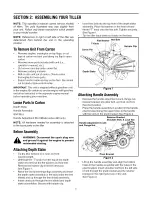
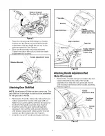
Page 5: ...ended starting Attaching DepthStake Tip the tiller forward so it rests on front counterweight Unthread the T knob from the top of the depth stake and remove the flat washer and hex bolt Remove the hairpin clip from the clevis pin See Figure 1 Raise the tine shield hinge flap assembly and insert the depth stake assembly in the slot under the tine shield and up through the tine shield assembly Inser...

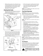
Page 6: ... be assembled on the right side on handle Remove the T handle hairpin clip flat washer and rubber washer from the end of the gear shift rod Slide the rod up through the right side of bracket on the front of the handle assembly See Figure 5 Insert the end of the gear shift rod through the opening in the top of the shift cover and into the shift bracket Secure with rubber washer first flat washer an...

Page 7: ...inst a solid object such as a wall With the gear selection lever in NEUTRAL start the engine Refer to Operation section NOTE Keep hands out of belt area while unit is operating Standing on the right side of the tiller visually examine the belt inside the belt cover It should not be turning If the belt turns with the unit in neutral adjust by moving the hex nut below the cable bracket down a few tu...

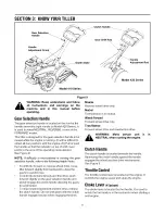
Page 8: ...e gear selection handle refer to the following helpful hints To shift into forward or reverse wheel drive move tiller forward slightly then backward to allow the gears to synchronize To shift into forward wheels and tine drive push forward slightly on the gear selection handle and slowly engage the clutch handle allowing the gears to synchronize To stop forward movement and tine drive release the ...

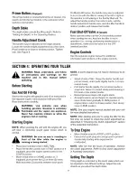
Page 9: ...ile the engine is hot or running StartingEngine NOTE When pushing the unit with the engine off you will hear a ratcheting sound gear noise which is normal _ WARNING Be sure no one is standing in front of the tiller while the engine is running or being started Place gear selection lever in NEUTRAL Place the throttle control lever in FAST position or if equipped place the engine speed control in the...

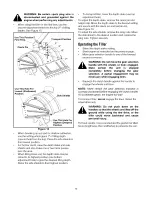
Page 10: ...th stake to the desired setting and secure with the clevis pin and hairpin clip See Figure 10 To adjust the side shields remove the wing nuts Move the side shield to the desired position and replace the wing nuts Tighten securely OperatingtheTiller Select the depth stake setting Start engine as instructed on the previous page Move gear selection handle to one of the forward modes or reverse WARNIN...

Page 11: ...mbled The spark plug should be cleaned and the gap reset every 25 hours of engine operation Spark plug replacement is recommended at the start of each tiller season check engine manual for correct plug type and gap specification Clean the engine regularly with a cloth or brush Keep the cooling system blower housing area clean to permit proper air circulation which is essential to engine performanc...

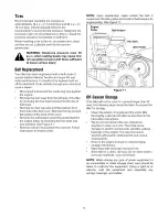
Page 12: ... belt keeper assembly located behind the engine pulley by removing two hex bolts and lock washers See Figure 11 Remove belt and reassemble the new belt Follow instructions in reverse order NOTE Upon reassembly make certain the belt is routed over the idler pulley and inside of belt keepers by engine pulley See Figure 11 Engine Pulley Belt Keeper Hex Bolt Idler Figure 11 0ff Seas0n Storage If the t...

Page 13: ...tabilizer is used Move throttle lever to start position Clean fuel line Refer to the engine manual packed with your unit Move choke to ON position Connect wire to spark plug Clean adjust gap or replace Refer to the engine manual packed with your unit Move choke lever to OFF position Connect and tighten spark plug wire Clean fuel line fill tank with clean fresh gasoline Fuel will not last over thir...

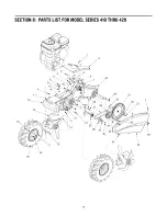
Page 14: ...SECTION 8 PARTSLISTFORMODEL SERIES 410THRU420 1 5 8 I 4 i 2 I 18 23 I 25 29 I I I I 26 3 32 40 1 39 14 ...

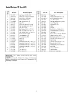
Page 15: ...6 Ref No 19 21 22 23 24 25 26 27 28 29 30 31 32 33 34 35 36 37 38 39 40 41 42 43 Part No 714 0104 710 1090 686 0031A 736 0119 710 0237 756 0971 756 0972 754 0438 756 0405 738 0899 736 0256 756 0634 736 0105 712 0379 736 0452 710 0152 786 0080 710 0723 738 0876 736 3020 786 0100 712 0392 786 0107 686 0094 Part Description Cotter Pin Flange Screw 5 16 18 x 1 25 Belt Keeper Bracket Ass y Lock Washer ...

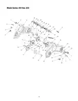
Page 16: ...ModelSeries410thru420 32 36 38 9 24 25 1 23 13 1 3 2 25 16 ...

Page 17: ...aft 5 8 Dia X 2 06 Lg Spacer 635 ID x 1 00D Wheel Shift Assembly Gear Case Assembly LH Half Hex Washer Screw 1 4 14 x 625 Plug Ball Bearing w Snap Ring Hex Patch L Nut 7 16 20 Ref No 29 30 31 32 33 34 35 36 37 38 39 40 41 42 43 44 45 46 47 48 49 50 51 52 53 Part No 786 0086 721 0295 710 0258 736 0329 736 0512 741 0124 736 0541 717 1451A 713 0435 736 0265 716 0235 718 0237 711 1087 732 0863 741 086...

Page 18: ...ModelSeries410 10_ 7 23 10 25 6 17 J j J J J J J j _ J J J J J J J v 32 17 42_ 43 18 ...

Page 19: ... 686 0043A Flange Lock Nut 3 8 24 43 786 0120 Spacer 322 ID x 625 OD 44 786 0077 Handle Adjustment Crank 45 710 3097 Hex Screw 5 16 18 x 3 0 46 714 0147 Handle Mounting Bracket LH 47 746 0916 Handle Mounting Bracket RH Part Description Cap Nut Rod Rear Tine Shield Flap Hex Cap Screw 3 8 16 x 1 25 Flat Washer 375 ID x 620 OD Hex Cap Screw 5 16 18 x 75 Hex Screw 5 16 18 x 75 Tine Shield Wing Nut End...

Page 20: ...ModelSeries420 4 5 1 34 25 Ii 2O ...

Page 21: ...0147 Flange Lock Nut 3 8 24 50 711 0415 Retainer Bracket 51 686 0043A Hex Flange Lock Nut 5 16 18 52 710 3038 Handle Adjustment Crank 53 712 0798 Hex Cap Screw 3 8 16 x 3 0 54 736 0169 Hex Cap Screw 5 16 18 x 3 0 55 786 0120 Part Description Handle Pivot Bracket Assembly Carriage Bolt 3 8 16 x 1 0 Handle Bracket Assembly Wing Nut Rubber Washer 33 ID x 87 OD Flat Washer 344 ID x 62 OD Cotter Pin Si...

Page 22: ...NOTES 22 ...

Page 23: ...NOTES 23 ...

Page 24: ... adjustments and normal deterioration of the exterior finish due to use or exposure Service completed by someone other than an authorized service dealer e f g MTD does not extend any warranty for products sold or exported outside of the United States its possessions and territories except those sold through MTD s authorized channels of export distribution Replacement parts that are not genuine MTD...

Reviews: