mr. steam MS-150, Installation, Operation & Maintenance Manual
The Sven MS-150 features cutting-edge technology, superior performance, and unrivaled durability. With its intuitive interface and comprehensive features, this revolutionary power tool ensures optimal efficiency. Take your productivity to new heights with the Sven MS-150 Operation Manual, available for free download at manualshive.com. Enhance your understanding of this remarkable product and unlock its full potential.
Share
Download


Reviews:
No comments
Related manuals for MS-150
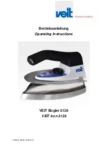
2129
Brand: Veit Pages: 11

VT-1225
Brand: Vitek Pages: 8

VG HST 3000
Brand: Venga Pages: 29

741-048
Brand: Ide Line Pages: 32

LUCEA ID
Brand: T3 Pages: 39

JFV019158
Brand: Jocel Pages: 30

Ironspeed SRD 4106
Brand: Hoover Pages: 121

TB 24450 UC
Brand: Siemens Pages: 2

SCC 35 A1
Brand: Silvercrest Pages: 14

SWC 300 A1
Brand: Silvercrest Pages: 39

Quick Curl SHC 240 B2
Brand: Silvercrest Pages: 32

108122
Brand: Silvercrest Pages: 45

276001
Brand: Silvercrest Pages: 51

SHGB 50 A1
Brand: Silvercrest Pages: 66

SHC 240 A1
Brand: Silvercrest Pages: 74

DAMPFBÜGELAUTOMAT BA 3267
Brand: SEVERIN Pages: 5

3285
Brand: SEVERIN Pages: 70

3242
Brand: SEVERIN Pages: 58


