Motorola GP200 Series, Service Manual
The Motorola GP200 Series is a reliable and high-performance radio communication system. For those seeking a detailed understanding of the device's functionality and maintenance, we offer the Service Manual for free download at manualshive.com. This comprehensive manual provides step-by-step instructions, troubleshooting tips, and essential information to ensure seamless operation of the GP200 Series.
Share
Download


Reviews:
No comments
Related manuals for GP200 Series

ORTUS 1
Brand: Roberts Pages: 40

DAB650
Brand: SOUNDMASTER Pages: 11

1201850
Brand: Radio Shack Pages: 12

Evoke D2
Brand: PURE Pages: 120

AE 4200 MC
Brand: Albrecht Pages: 16

GTX 45R
Brand: Garmin Pages: 69

HP-528
Brand: Matsutec Pages: 25

UV-82
Brand: Baofeng Pages: 25

MR003G
Brand: Makita Pages: 91
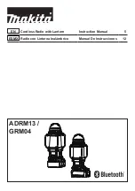
ADRM13
Brand: Makita Pages: 20

DMR102
Brand: Makita Pages: 100

MR002G
Brand: Makita Pages: 129

MR051
Brand: Makita Pages: 24

MR005G
Brand: Makita Pages: 17

Outdoor Adventure ADRM06
Brand: Makita Pages: 25
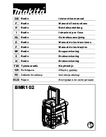
BMR102
Brand: Makita Pages: 19

100579
Brand: Makita Pages: 135

DMR106
Brand: Makita Pages: 116


