Morgana UFO, Operator'S Manual
The BlueTrek UFO user manual is a comprehensive guide to unlocking the full potential of this innovative product. As a Supplementary Manual, it provides in-depth instructions for seamless connectivity, optimal performance, and advanced features. Download this manual for free from our website manualshive.com, and enjoy harnessing the power of the BlueTrek UFO.
Share
Download


Reviews:
No comments
Related manuals for UFO
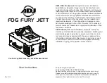
FOG FURY JETT
Brand: ADJ Pages: 10

Sweepmaster P1500 RH
Brand: HAKO Pages: 80

BR 40/10 C Classic
Brand: Kärcher Pages: 196

RootsScrub B6050
Brand: ROOTS Pages: 22

99K Series
Brand: Singer Pages: 78

DKS100 SE
Brand: Janome Pages: 61

Truvox International Orbis Compact
Brand: Tacony Pages: 14

Pulsar E 300
Brand: Fellowes Pages: 54

Tiara BLTR16
Brand: Baby Lock Pages: 33

Modular TL2900
Brand: GBC Pages: 38

Sniper 2-100
Brand: Sandia Plastics Pages: 13

Rondo
Brand: Necta Pages: 45

B430
Brand: Bartell Pages: 47

88 762 57
Brand: Vix Pages: 11

CM1250
Brand: Seaga Pages: 8

CLASSIC DUAL
Brand: Pop-A-Shot Pages: 15

Advance 9087381020
Brand: Nilfisk-Advance Pages: 68

50000593
Brand: Nilfisk-Advance Pages: 107


