background image

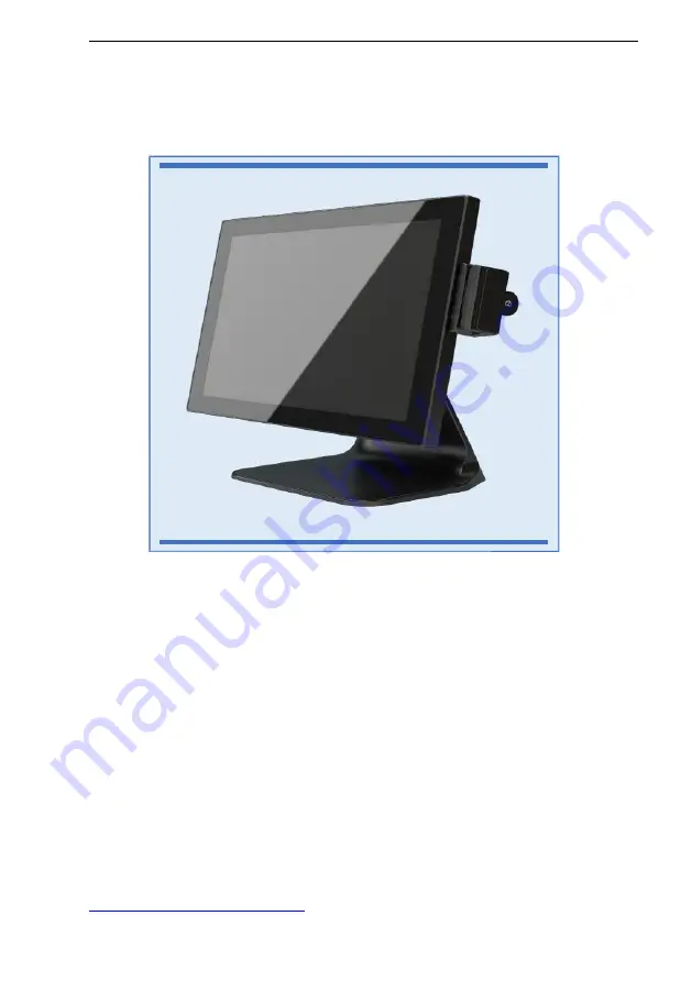
GTA Touch screen EPOS system

operating, installation &

maintenance manual v 1.1

Thank you for choosing Monitor touch screen products, this manual is for GTA-

A8 TC-Touch. Before installing and using the product, please read this manual.

Keep this manual for future use.

This manual contains the latest information as of supply date. We reserve the

right to update or improve the product without notification.

This equipment must be installed by qualified service personnel or distributor.

The company assumes no responsibility for unauthorised changes to the

equipment.

Monitor POS Ltd

8 Church Street, Godalming, Surrey, GU7 1EH

email

[email protected]

www.monitorpos.co.uk

- 1 -

Summary of Contents for GTA-A8 TC-Touch

Page 1: ...ep this manual for future use This manual contains the latest information as of supply date We reserve the right to update or improve the product without notification This equipment must be installed by qualified service personnel or distributor The company assumes no responsibility for unauthorised changes to the equipment Monitor POS Ltd 8 Church Street Godalming Surrey GU7 1EH email info monito...

Page 2: ...nto the POS machine 7 6 Refitting the coms port cover 8 7 Specifications 9 8 Preparations before use 9 9 POS System layout 10 Appendix 1 Product description 15 Appendix 2 Technical parameters 16 Appendix 3 J1900 controller layout 17 Appendix 4 Touch calibration 18 20 Appendix 5 Touch FAQ 21 Warranty 22 2 POS System layout 13 POS System layout 11 11 10 ...

Page 3: ... socket voltage matches the voltage on the nameplate 6 Do not connect to a power socket or circuit shared with other high power appliances We recommend use of a spike and surge protected socket 7 Secure input power cables to avoid live unplugging of the system 8 When cleaning do not use a wet cloth or chemical wipe for the body such as solvents or thinners etc A standard domestic glass cleaner spr...

Page 4: ...company and to supplier After unpacking you should also check whether the contents which should include CONTENTS Touch screen EPOS system Software and driver CD 5A x 12VDC Power supply 230VAC mains power lead 2 Preparing for Installation Check whether the housing is clean and undamaged and marking and labelling is correct Check the work environment See Safety precautions on previous page 4 ...

Page 5: ...ews medium size flat orcrossheadbladed driver recommended until the back looks as below Note that the panel is secured at the top edge so you must lift the BOTTOM edge first Rear panel with two screw fixing securing points Pull up or lever up so that BOTTOM edge opens first 5 ...

Page 6: ...emoved for the first time the process is easier Place unit face down as shown and lever up one side until you hear the loud click of disconnection Then do the same on other side and gripping the partly lifted open base lift upwards and forwards come off The plastic trim will Monitor will replace free of charge any plastic trim panels damaged in the installation process To refit simply push in plac...

Page 7: ... passing when bulky the connectors tilt the angle of the screen to make the access hole larger Coms area showing best angle for Max clearance Larger RS232 serial cables need to be run OUTSIDE if they cannot pass through 7 5 Connecting cables into POS machine port area ...

Page 8: ...ting the metal coms cover Refitting the top cover is simple just insert the top edge first then push in place and refasten the two thumbscrews Close up showing multiple cables threaded through with strain relief ...

Page 9: ...ystems Software settings are Com Port 2 Character set standard US To Install Remove the port cover as shown in 3 above and pop out from behind the plastic insert that sits above the customer display mounting points as shown Identify the top of the display to avoid mounting it upside down The BOTTOM is identified by the slot in the mounting extrusion and the small moulding mark ...

Page 10: ...er display using the M5 screws supplied Connect the display cable to the small cable which is prewired to com 2 and sits ready in the port area The connector provides both power and data and is polarized so impossible to misconnect Check the connector lock has clicked in place Refit the port cover power up and test ...

Page 11: ... The screen comes with all cables and a complete replacement port cover for easy fitting There are 2 connections to make It is recommended that the complete assembly be removed for any cable maintenance Connect the white ribbon cable to the box header visible just inside the main casing Connect the TFT power cable to the DC output then carefully coil the ribbon cable and refit the port cover scree...

Page 12: ... if you don t do this Plug in a mouse and right mouse click on the main desktop Select Graphics Options Panel Fit Monitor and check the Maintain Display Scaling option Then select Graphics options Output to Extended desktop then check Built in Display Monitor ...

Page 13: ...8 Preparation before use 1 Keep cables tidy and routed to avoid strains or stresses Use the cable tidy system on the unit to have all cables exiting from rear base 2 Be sure to ensure a good supply ground 3 Supplied with Windows 7 Pro which should be licensed prior to use 4 Check the display touch screen and other peripherals work properly 13 ...

Page 14: ... 2 6 1 15 inch five wire resistive screen or Multi point capacitive 2 Power on button 3 2 x USB external 4 Optional 2 20 LCD or VFD customer display 5 Optional MSR Rfid Ibutton all in one 6 Optional 10 1 TFT 1280 800 14 ...

Page 15: ...rk Temperature 0 50 Store temperature 40 70 Relative humidity 95 60 Precise tolerances 0 5 Reaction time 35 ms MTBF 50 000 Touch force 20 120g Positional deviation 3 5 mm Reaction time 5 Millisecond Authenticate CE FCC ROHS Size 326mm x 252mm 15 1 inch Viewing area 304mm x 228mm 4 3 Resolution 1024 x 768 Standard Refresh Rate 60Hz Pitch 0 297mm x 0 297mm Colour 16M Response time 16ms ...

Page 16: ...4 768 HDD 64G SSD COM 2 Interface IDE 1 Interface SATA 2 Interface USB2 0 8 Interface 4 on com panel 2 external on side 2 internal on J1900 Power AC 100 240V Chipset Intel Bay Trail D SoC LAN Embedded RTL8111C CPU Integrated Intel Bay Trail D j1900N 2 0G RAM DDR3 4GB Customer Display 2 20 LCD or VFD POS Printer See Monitor website for Xprinter range ...

Page 17: ... 3 MAIN Board connectors Figure J1900N 17 ...

Page 18: ...1 Touch panel calibration and setting for resistive screens Note that capacitive screens are adjusted through Windows Pen options 18 ...

Page 19: ...This interface can be set to the touch Beep or No If when you touch the cursor is too far away from your touch point you can use 4 point calibration or for more accuracy 9 point 19 ...

Page 20: ...linearization Touch each X until it stops Press OK after Calibration 20 ...

Page 21: ...se icon appears square or similar appearance shape depends on the drive icon on the version the user changes as below if required Right click on the system tray Touchkit icon select the pop up options in the button setting Touch failure or intermittent malfunction Turn off the system s power saving mode USB device re plug the USB Interface The cursor always stays at a certain position Check that t...

Page 22: ...ilure or damage 3 Unexpected factors or man made reasons scratches handling impact improper input voltage and current etc leading to products including peripherals fault or damage including appearance 4 Product failure or damage due to natural disasters and other force majeure such as earthquakes fire etc 5 Product failure or damage caused due to the use of oxidation products short circuit and oth...

Reviews: