


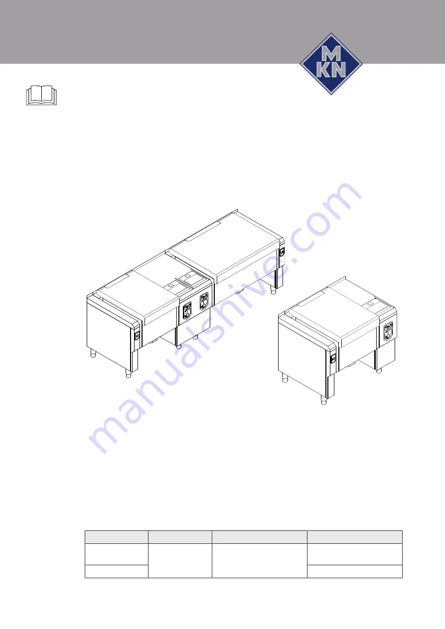
Installation instructions
FlexiChef
Unit
Energy type
Design
Model
FlexiChef
Electric
Deep-frying
High-speed cooking
Cleaning
FCEKMP1XXXX-----
G2
...
FCEKMP3XXXX-----
G2
...
FlexiChef Team
FCEKMP2XXXX-XXXX
G2
...
Translation from the original document • 10000008311AINDEB • 01/04/2020
10000008311AINBEB
en-GB
Read the operating instructions prior to
commissioning
Summary of Contents for FlexiChef FCEKMP12 Series
Page 64: ...Putting the unit into service 64 Installation instructions 10000008311AINBEB ...
Page 65: ......
Page 66: ......
Page 67: ......
Page 68: ...www mkn com ...


