


RedLINK™ Wireless
Remote Controller Kit
Installation Manual
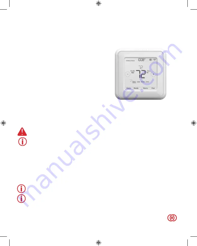
MHK2:
MRCH2 Controller, MIFH2
Receiver, and MRC2 Cable
DISCONNECT POWER
BEFORE BEGINNING INSTALLATION
.
Can cause electrical shock or equipment damage.
Must be installed by a trained, experienced technician
.
Read these instructions carefully. Failure to follow these instructions can damage the product or cause a
hazardous condition.
Installation at a Glance
This manual covers the installation and setup of the MHK2 Remote Controller with Mitsubishi Electric
indoor units.
Before you begin, you must attach the cable to the CN105 connector on the indoor unit control
board, then follow the steps in this document.
Note:
Remote Controllers are linked to specific indoor units. Each indoor unit must have a
dedicated Remote Controller and Wireless Receiver.
Note:
Your device's PIN code is your date code added to 1234. For example, a date code of
2010 plus 1234 would give you a device PIN of 3244.
© 2019 Mitsubishi Electric US, Inc.
Suwanee, GA 30024 All Rights Reserved.
https://mhk2.meushvac.com/
1-800-433-4822
MHK2 is compatible
with kumo cloud
®
when
connected with the Wireless
Interface 2 or later.
RedLINK
Technology
33-00446EFS_B.indd 1
10/17/2019 3:08:58 PM


