Miele ESW4710, Technical Information
The Miele ESW4710 user manual can be easily accessed for free download from our website. It provides comprehensive Technical Information and step-by-step instructions on operating and maintaining your Miele ESW4710 appliance. Browse our site today and unlock the full potential of your product.
Share
Download


Reviews:
No comments
Related manuals for ESW4710
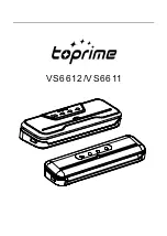
VS6611
Brand: toprime Pages: 36

buubibottle
Brand: Quark Pages: 14

18310003
Brand: Gastronoma Pages: 43

39853
Brand: Omcan Pages: 16

SE-CN-0203
Brand: Omcan Pages: 12

TC-420
Brand: Omcan Pages: 17

Lighted
Brand: Star Manufacturing Pages: 2

C5 6 series
Brand: Metro DataVac Pages: 21

GVS1000
Brand: Metro DataVac Pages: 99

VP115
Brand: Vacmaster Pages: 16

Ranger 245
Brand: Arizant Healthcare Pages: 17

CLH810
Brand: Jata electro Pages: 20

VAC 6000
Brand: Taurus Pages: 48

BABYUNO
Brand: CANGAROO Pages: 48

BMA7102
Brand: Anvil Pages: 1

natural flow Insta-Feed AC184
Brand: DrBrowns Pages: 15

Universal Warmer UW-17
Brand: BKI Pages: 12

BW-512 CAR
Brand: Alecto Pages: 24


