Micros Systems Workstation 4, Service Manual
The Micros Systems Workstation 4 is a versatile and advanced computing solution for businesses. Our comprehensive Setup Manual is available for free download at manualshive.com, ensuring hassle-free installation and smooth operations. Enhance productivity with this user-friendly manual, providing step-by-step instructions and valuable insights for optimal utilization.
Share
Download


Reviews:
No comments
Related manuals for Workstation 4
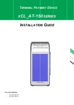
XCL AT-150 SERIES
Brand: XAC Pages: 8

EZPOS70-2B-C1G
Brand: EBN Technology Pages: 21

POS-6000 Series
Brand: Fametech Pages: 35

POS 460 Series
Brand: Axon POS System Pages: 46

VIVOpay VP8800
Brand: IDTECH Pages: 21

NS10-TV Series
Brand: Omron Pages: 682

EW Series
Brand: ESA Pages: 6

ASTRO 25 DT-5365 Series
Brand: Design 2000 Pages: 30

Unifix AD 1STQ004320B0000
Brand: ABB Pages: 2

i3070 CL
Brand: Ingenico Pages: 2

CI 3000 - COMPATIBILITY LIST
Brand: VDO Pages: 13

TM-550
Brand: EBN Technology Pages: 12

OT-310
Brand: Partner Pages: 28

ProBio(QR)
Brand: ZKTeco Pages: 71

Data Entry Terminal 8620 Installation and opertions
Brand: Varec Pages: 40

CURS100
Brand: Campbell Pages: 18

POS Mobile XL
Brand: Vectron Pages: 148

Verifone VX 520
Brand: tupago Pages: 5


