background image


Air Assisted Vehicle Mounted ULV and LV Sprayer


Operator’s Manual & Parts Catalogue


Summary of Contents for AU8115MS

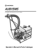
Page 1: ...Air Assisted Vehicle Mounted ULV and LV Sprayer Operator s Manual Parts Catalogue...

Page 2: ......

Page 3: ...tor s Manual and Parts Catalogue Micron Sprayers Limited Bromyard Industrial Estate Bromyard Herefordshire HR7 4HS United Kingdom Tel 01885 482397 44 1885 482397 Fax 01885 483043 44 1885 483043 E mail...

Page 4: ......

Page 5: ...e Forward Speed of the Vehicle 12 6 2 Select a Suitable Track Spacing 12 6 3 Calculate required Flow Rate from the Sprayerr 13 6 4 Set the Flow Rate 14 6 5 Select the Correct Droplet Size 16 7 SPRAYIN...

Page 6: ......

Page 7: ...products The sprayer can be used for flow rates from 0 2 3 5 litres per minute The sprayhead is driven by a high velocity air stream produced by a blower powered by a reliable 4 stroke engine with el...

Page 8: ...e Flow rate adjustment By manually adjustable restrictor valve or by interchangeable restrictor orifice discs Pump 12 V magnetically coupled centrifugal pump Spray droplet size 40 100 microns VMD depe...

Page 9: ...3 MICRON AU8115MS VEHICLE MOUNTED SPRAYER Fig 1 Components of AU8115MS Sprayer...

Page 10: ...Sprayer The AU8115MS sprayer is shipped partially dismantled and must be assembled prior to use The procedure for setting up a new sprayer is as follows 1 Position the lower ends of the sprayhead sup...

Page 11: ...battery cable into the receptacle on the battery leads 15 Secure the cable in the engine compartment with the cable ties provided Ensure that the cable is well clear of sharp edges and all moving or...

Page 12: ...e or diesel oil in the 10 litre tank Rotate the two way valve towards the rear of the sprayer to select the 10 litre tank and ensure that the isolation valve near the filter is open Angle the spray he...

Page 13: ...d by moving fully to the left when the sprayer is not in use 2 Engine choke lever grey mounted on the side of the engine above the fuel valve The choke lever should be in the OPEN position fully to th...

Page 14: ...ch on the engine to the ON l position with the key vertical IMPORTANT The engine will not start if the key switch is set to the anti clockwise O STOP position 3 Set the THROTTLE switch on the control...

Page 15: ...et the ENGINE switch on the control box to the central RUN position 2 Set the key switch on the engine to the ON l position key vertical IMPORTANT The engine will not start if the ENGINE switch on the...

Page 16: ...YS wear appropriate protective clothing during filling and calibration 3 DO NOT spray near people or domestic animals There should be no people or domestic animals within 200 metres downwind from wher...

Page 17: ...Do not operate the engine if the air cleaner or the cover directly over the carburettor air intake is removed 7 When transporting the sprayer the fuel shut off valve must be closed to prevent fuel lea...

Page 18: ...pacing is the distance between successive spray passes of the vehicle Spray passes should always be made with the wind at right angles to the direction of travel of the vehicle Although the peak spray...

Page 19: ...ume application rate is chosen so as to apply the recommended dose of active ingredient see FAO guidelines or manufacturer s label Example if required volume application rate 0 5 litres per ha l ha Ve...

Page 20: ...flow rate are required as it eliminates the need to disconnect pipe fittings and the consequent risk of exposure to pesticide To set the flow rate 1 Park the vehicle facing into the wind with the spr...

Page 21: ...ibration 8 If the flow rate is too low or too high fit a larger or smaller orifice plate or select a larger or smaller restrictor valve setting as appropriate and repeat steps 5 9 Actual flow rate wil...

Page 22: ...liquid flow rate The relationship between atomiser blade angle setting flow rate and atomiser rotational speed is given in the table and graph below Atomiser Speed RPM Blade Setting Number Flow l min...

Page 23: ...spraying it must be driven upwind of the target and in a direction at 90 to the wind The spray head should be angled upwards to achieve maximum effective release height and a wide swath or it should...

Page 24: ...be left in the sprayer when it is not in use 7 3 Additional Applications The spray head may be de mounted from the gimbal mounting ring and held by an operator to direct spray towards a specific targe...

Page 25: ...the fan cover and guard Remove the cover and guard 2 Thoroughly clean the fan vanes and back plate of the fan and inside of the casing using a stiff brush and compressed air if available 3 If the are...

Page 26: ...tres of kerosene or other suitable solvent through the atomiser at the end of each spray job Water will normally only dissolve water based formulations whereas kerosene or diesel fuel is suitable for...

Page 27: ...tion Bearings 13 Both in good condition If one bearing is faulty both must be replaced together Tolerance rings 16 Not cracked or deformed Bearing spacers 6 and 7 Not corroded or worn V Ring seal 14 I...

Page 28: ...r replace filter Clean see engine maintenance handbook Refer to qualified mechanic or local Briggs Stratton service centre No flow Orifice restrictor plate blocked Blocked variable restrictor valve Bl...

Page 29: ...nnector and battery cables Locate fault and replace fuse 100 A Locate fault and reset CONTROLS circuit breaker Engine throttle does not move between maximum and minimum settings when THROTTLE switch i...

Page 30: ...are parts please specify the following information 1 Serial number of sprayer or engine 2 Approximate date of purchase 3 Description of part 4 Part number as shown in this section 5 Number of parts re...

Page 31: ...l 1 10 EX6550 Atomiser assembly 1 12 EX6531 Fan housing 1 13 EX6529 Air intake guard 1 14 5922 Pump cover 1 15 EX6730 Pivot pin 10 mm dia 4 16 5671 R clip 6 17 EX6729 Locking pin 12mm dia 1 18 CBP3855...

Page 32: ...26 MICRON AU8115MS VEHICLE MOUNTED SPRAYER AU8115MS Main Components Continued Fig 12 AU8115MS Main Components Continued...

Page 33: ...71 EX6835 Washer tab 1 72 CBP447 Grommet 1 73 AJ6418 Cable tie 2 74 CBP2865 Cable gland 20 mm 2 75 EX6860 Bracket needle valve 1 76 AJ6187 Conduit nylon 4m 77 4693 Screw 4BA x 7 8 2 78 3667 Nut 4 BA...

Page 34: ...28 MICRON AU8115MS VEHICLE MOUNTED SPRAYER 10 2 AU8115MS Pipework Components 29 Fig 13 AU8115MS Pipework Components...

Page 35: ...2 port 2 27 5901 Valve 3 port 1 28 CBP2874 T piece 1 2 BSP F F 1 2 BSPT M 1 29 EX7090 Adaptor 1 2 BSP M M P T 5 30 CBP2895 Swivel adaptor 1 2 BSPT M 1 2 BSPP F 3 31 CBP2873 Adaptor 1 2 BSP M M P P 1...

Page 36: ...30 MICRON AU8115MS VEHICLE MOUNTED SPRAYER AU8115MS Pipework Components Continued 29 Fig 13 AU8115MS Pipework Components Continued...

Page 37: ...EX6907 Hose tank to 3 way valve 1 47 EX6908 Hose flushing tank to 3 way valve 1 49 EX6900 Hose drain 1 56 6003 Nut M17 1 57 AJ6379 Body LFM 1 4 BSP brass 1 84 AJ6337 Orifice restrictor plate No 24 1...

Page 38: ...nents Parts List ITEM PART NO DESCRIPTION QTY 1 EX4675 AU 8115 atomiser 1 2 EX4676 Front casing assembly 1 3 EX6540 Rear casing assembly 1 4 EX4622 Support ring 1 5 EX2275 Bush 1 6 EX2701 Washer 1 7 C...

Page 39: ...bly 1 3 EX3669 Clamp ring 1 4 EX3676 20 Gauze assembly 1 5 EX4641 Cap and deflector 1 6 EX3685 Inner spacer 1 7 EX3686 Outer spacer 1 8 EX3670 Spacer bush 1 9 EX4681 Blade 4 10 EX5044 Sealing ring 1 1...

Page 40: ...sher 2 BA shakeproof 4 2 5766 Drive magnet complete with grub screw screw 1 3 5767 Pump motor bracket PP blue 1 4 5768 Screw M5 x 12mm ch head 4 5 5770 Pump body 1 2 BSP in out 1 6 5771 Impeller 10 po...

Page 41: ...ts Fig 17 5881A Filter Components 5118A Filter Components Parts List ITEM PART NO DESCRIPTION QTY 1 5881 Filter body 1 2 BSP female 50 mesh pressure line 1 2 AJ6146 O ring in line filter viton 1 3 540...

Page 42: ...ectric Throttle Actuator Components ITEM PART NO DESCRIPTION QTY 1 EX7462 Actuator sub assembly 1 2 EX7219 2 Box lid 1 3 CBP3362 Screw M4 x 10 2 4 CBP2608 Nut M4 nyloc 2 5 CBP2226 Washer M6 plain 2 6...

Page 43: ...BLACK BROWN RED RED BLACK GREEN BLUE TB1 TB2 1 2 3 4 ENGINE LOOM CONNECTOR VIEW ON CABLE ENTRY SIDE OF PLUG VIEW ON CONTACT SIDE OF SOCKET 1 CONTROL BOX CONNECTOR VIEW ON CABLE ENTRY SIDE OF PLUG VIE...

Page 44: ......

Page 45: ...hectare 107600 sq feet 11955 sq yards 1 hectare 10000 sq metres 2 47 acres 1 sq mile 640 acres 259 hectares 1 sq kilometre 247 acres 100 hectares 1 US gal 0 83 Imp gal 3 78 litres 1 Imp gal 1 20 US g...

Page 46: ...d the preparation of this manual However Micron Sprayers Limited cannot accept responsibility for errors or the consequences thereof Users must satisfy themselves that the equipment is suited to the i...

Reviews: