Microelettrica Scientifica MC20-CEI, Operation Manual
The Microelettrica Scientifica MC20-CEI is a cutting-edge electrical control gear product designed for efficient operation. Access the free Operation Manual for this high-quality device for detailed instructions on usage and maintenance. Download the manual from manualshive.com to maximize the performance of your MC20-CEI.
Share
Download


Reviews:
No comments
Related manuals for MC20-CEI

C Series
Brand: Eaton Pages: 8

710-00792-1
Brand: Sanyo Pages: 8
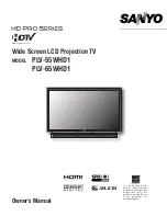
PLV-55WHD1
Brand: Sanyo Pages: 35

PLC-XR70N - 70" Rear Projection TV
Brand: Sanyo Pages: 46

PLV-45WR1Z
Brand: Sanyo Pages: 72
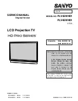
PLV-55WHD1
Brand: Sanyo Pages: 176

CLASSIC DX Series
Brand: CENS Pages: 40

RMT/1
Brand: Thytronic Pages: 4

XMR-A 4l+1A
Brand: Thytronic Pages: 384

633711
Brand: Silverline Pages: 2

Home Theatre P52928
Brand: RCA Pages: 4

SP50L7HX
Brand: Samsung Pages: 64

55PP8620 Matchline
Brand: Philips Pages: 2

GRD140
Brand: Toshiba Pages: 20

ICM441
Brand: ICM Controls Pages: 2

I2R SuperHy 120
Brand: Transtector Pages: 2

PR3032NK
Brand: Prorack Pages: 8

WaluCover Initial
Brand: Walter Pages: 20


