MFJ MFJ-4416B, Instruction Manual
The MFJ MFJ-4416B is a versatile device, ideal for amateur radio enthusiasts. This high-performance equipment comes with an Instruction Manual for easy setup and operation. You can conveniently download this comprehensive manual for free at manualshive.com, ensuring a seamless user experience with your new MFJ MFJ-4416B.
Share
Download


Reviews:
No comments
Related manuals for MFJ-4416B

39841
Brand: Metabo Pages: 5
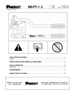
MSPT-1.3
Brand: Panduit Pages: 6

CT1082
Brand: Neilsen Pages: 10

VF1245
Brand: VADANIA Pages: 5

Universal CPU Holder
Brand: Ergotron Pages: 14

DAKE Force 25DA
Brand: Laguna Tools Pages: 15

67301
Brand: BGS technic Pages: 16

Ax-Press 25 22 V ACC
Brand: REMS Pages: 168

1.610.131
Brand: Ebinger Pages: 56

CC150MOB Series
Brand: Custom Crimp Pages: 15

02823
Brand: Gude Pages: 44

4040849511912
Brand: Goobay Pages: 10

8101S
Brand: King Canada Pages: 9

PAL+ 6715
Brand: NEBO Pages: 2

AP1840 Series
Brand: Wacker Neuson Pages: 46

M12 2448-20
Brand: Milwaukee Pages: 11

KIT SEK 100W
Brand: SALKI Pages: 20

P635B
Brand: Senco Pages: 11


