

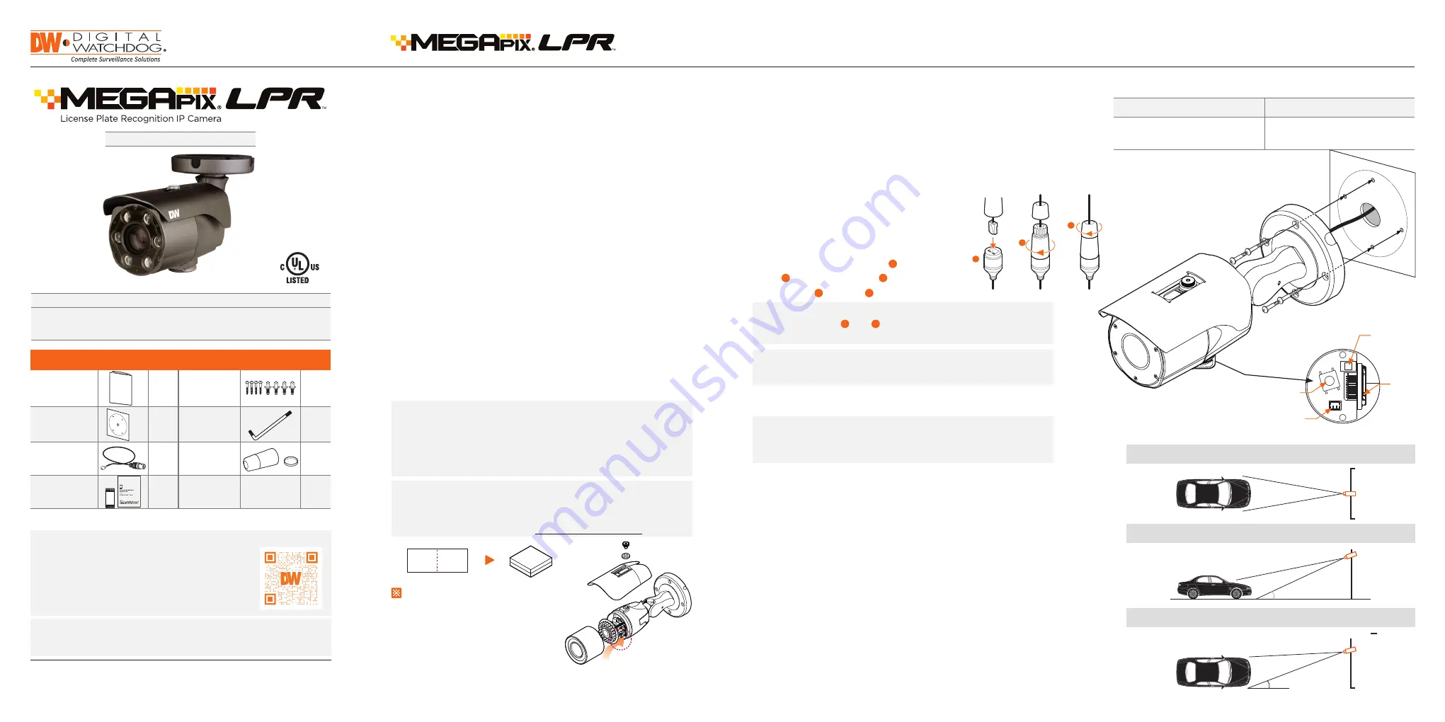
THE CAPTURED IMAGE SHOULD BE FILLED WITH THE FULL WIDTH OF THE VEHICLES
THE CAMERA SHOULD BE MOUNTED AT AN ANGLE NO GREATER THAN 30 DEGREES
CAMERA ANGLE NO GREATER THAN 20 DEGREES FOR SIDE MOUNT INSTALLATIONS
>11.5ft
< 30°
< 20°
Quick Start Guide
Tel: +1 (866) 446-3595 / (813) 888-9555
Technical Support Hours:
9:00 AM – 8:00 PM EST, Monday through Friday
digital-watchdog.com
Attention:
This document is intended to serve as a quick reference for initial
set-up. It is recommended that the user read the entire instruction manual for
complete and proper installation and usage.
NOTE:
Download all your support materials and tools in one place
1. Go to:
http://www.digital-watchdog.com/resources
2. Search your product by entering the part number in the
‘Search by Product’
search bar. Results for applicable
part numbers will populate automatically based on the
part number you enter.
3. Click
‘Search’
. All supported materials, including manuals
and quick start guide (QSGs) will appear in the results.
DWC-MB45iALPRT
WHAT’S IN THE BOX
Quick Setup and
Installation Guide
1
Screws and
Plastic Anchors
– 4pcs
1 set
Mounting
Template
1
Star Wrench
1
Test Video Cable
1
Waterproof Cap
and Gasket
1 set
Moisture
Absorber
and Guide
(Recommended)
1 set
LPR INSTALLATION GUIDELINES
Resetting the camera: To reset the camera, use the tip of a
paper clip or a pencil and press the reset button. Pressing the
button for five (5) seconds will initiate a camera-wide reset of
all the settings, including network settings.
Quick Start Guide
Default Login Information: admin | admin
When logging into the camera for the first time, you will be prompted
to set up a new password. You can set the new password using the
DW® IP Finder™ software or directly from the camera’s browser menu.
1. Once all cables are connected, secure the camera
to the mounting surface using the included screws.
2. To use the camera’s waterproof wiring:
a. Install the LAN cable into .
b. will be assembled to with a 1/4 turn.
c. Thread tightly to .
3. Loosen the pan and tilt screws at the base of the camera’s bracket to
adjust the camera’s view and position.
STEP 1 – PREPARING TO MOUNT THE CAMERA
STEP 3 – INSTALLING THE CAMERA
a
a
b
b
c
NOTE:
To ensure moisture seal, make sure the o-ring is in place
between and . In extreme environments use of an
outdoor rated sealer is recommended.
a
b
NOTE:
When using the waterproof cap, crimp the RJ45
connector after passing the cable through the
waterproof cap.
1. The mounting surface must bear five times the weight of
your camera.
2. Do not let the cables get caught in improper places or the electric line
cover to be damaged. This may cause a breakdown or fire.
3. CAUTION: These servicing instructions are for use by qualified service
personnel only. To reduce the risk of electric shock do not perform any
servicing other than that contained in the operating instructions unless
you are qualified to do so.
4. This product is intended to be supplied by a UL Listed Power Supply
Unit marked “Class 2” or “LPS” or “PS2” and rated 12 Vdc, 0.75A min.
5. The wired LAN hub providing power over the Ethernet (PoE) in
accordance with IEEE 802-3af shall be a UL Listed device with the
output evaluated as a Limited Power Source as defined in UL60950-1
or PS2 as defined in UL62368-1.
6. Unit is intended for installation in a Network Environment 0 as defined
in IEC TR 62102. As such, associated Ethernet wiring shall be limited to
inside the building.
7. Install the moisture packet in the base of the camera’s lens.
a. Remove the moisture absorber from the packaging.
b. Cut the card and folder along the dotted line.
c. Place the moisture absorber behind the camera’s lens module. See
drawing for more information.
8. Using the mounting template sheet or the camera itself, mark and
drill the necessary holes in the wall or ceiling.
Test video
output
Reset button
Zoom lens
button
SD card
input
a
b
c
WARNING:
It is highly recommended that you install the moisture
absorber when mounting the camera. The moisture
absorber prevents moisture from being captured
inside the camera's housing, which may cause image
performance issues and damage the camera.
NOTE:
The camera will generate enough heat to dry moisture
during operation. In most cases it will not need the
moisture absorber for more than the first day. In cases
where the camera can experience a moisture issue,
users must keep the moisture absorber in the camera.
The moisture absorber has an approximately 6-month
life cycle, varying depending on the environment.
STEP 2 – POWERING THE CAMERA
Power requirements
Power consumption
DC12V, PoE
(IEEE 802.3af class 3).
Adapter not Included.
DC12V Max 9W
PoE Max 10.5W
Pass the wires through and make all the necessary connections. See STEP 4.
1. When using a PoE Switch or PoE Injector, connect the camera using an
Ethernet cable for both data and power.
2. When not using a PoE Switch or PoE Injector, connect the camera to the
switch using an Ethernet cable for data transmission and use a power
adapter to power the camera.
• The LPR camera should be mounted at a height between 3~8 ft., and
a distance no greater than 80 ft. from the target area. Exceeding
the distance recommendations may result in a poor quality image
of moving license plates.
• Ensure that the camera angle is no more than 20° degrees
(horizontally) 30° degrees (vertically) from the target area.
• It is recommended to position a license plate or vehicle to reflect
the IR light of the camera while adjusting the camera’s focus of the
target area.
• After mounting the camera, you can press the Zoom Lens Button
(located on the underside of the camera) to sequentially zoom and
auto-focus the camera. Alternatively, the camera’s web GUI or
management software can be utilized as well. The longer the Zoom
Lens button (T-W jog button) is pressed down, the further the lens
module will zoom.
• Please note that the cameras ship with focus in Manual mode. To
change the camera’s focus to Auto, enter the camera’s web GUI and
use the +/- zoom buttons on the left of the camera image.
Attach additional moisture absorbers(card type)
Installation Guide
Outdoor Camera Waterproof
Absorber attachment point
Please cut the card type absorber along
a dotted line, overlap and attach them
according to the direction of the arrow.
2. Assemble the front cover with moisture absorber into the body.
1. Remove the packaging for the moisture absorber provided as an accessory.
3. How to attach the absorber(s).
: Refer to the picture at the bottom.
The whole process of [Cover Seperation - Attach Moisture Absorber - Close Cover]
If the package is removed from the accessory moisture absorber,
- do not get close to water.
Do not leave it without the cover for more than 10 minutes.
Do not install it in a humid environment.
(Dome moisture or dew formation can be caused.)
The accessory moisture absorber is provided in a sealed package.
It can be used to prevent the moisture(dew formation) that can occur as a result of water
entering the set during the product installation procedure(cover separation).
Attach accessory moisture absorbers (card type)and close the cover.
Please cut the absorber along the
dotted line, overlap and attach them
according to the direction of the arrow.
Attach additional moisture absorbers(card type)
Installation Guide
Outdoor Camera Waterproof
Absorber attachment point
Please cut the card type absorber along
a dotted line, overlap and attach them
according to the direction of the arrow.
2. Assemble the front cover with moisture absorber into the body.
1. Remove the packaging for the moisture absorber provided as an accessory.
3. How to attach the absorber(s).
: Refer to the picture at the bottom.
The whole process of [Cover Seperation - Attach Moisture Absorber - Close Cover]
If the package is removed from the accessory moisture absorber,
- do not get close to water.
Do not leave it without the cover for more than 10 minutes.
Do not install it in a humid environment.
(Dome moisture or dew formation can be caused.)
The accessory moisture absorber is provided in a sealed package.
It can be used to prevent the moisture(dew formation) that can occur as a result of water
entering the set during the product installation procedure(cover separation).
Attach accessory moisture absorbers (card type)and close the cover.


