background image


1


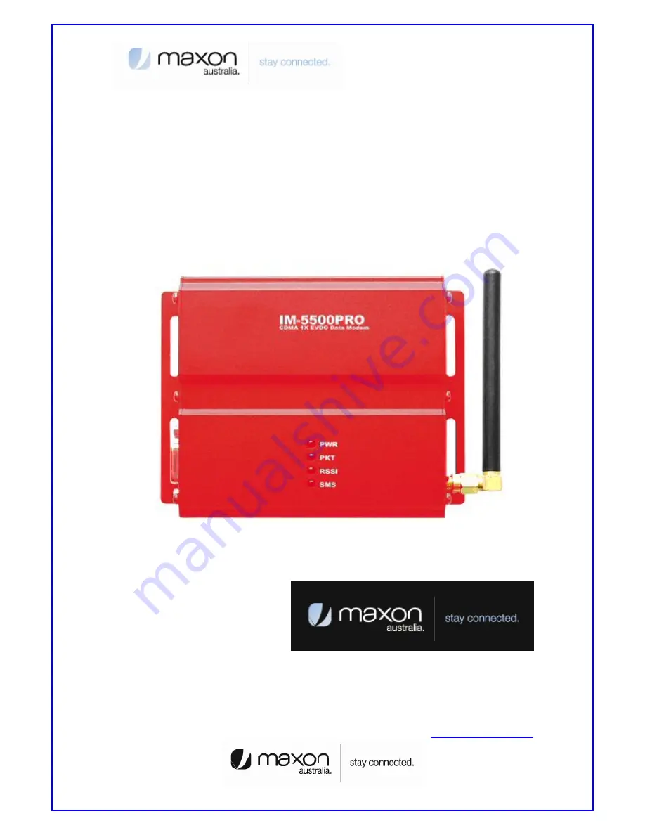
MM-5500PRO Quick Start Manual 

Wireless CDMA 1x EVDO Ethernet modem 


Technical Support: [email protected] 

TEL : 61 2 9707 2000 

FAX : 61 2 9707 3328 


www.maxon.com.au

Summary of Contents for MM-5500PRO

Page 1: ...1 MM 5500PRO Quick Start Manual Wireless CDMA 1x EVDO Ethernet modem Technical Support engineering maxon com au TEL 61 2 9707 2000 FAX 61 2 9707 3328 www maxon com au ...

Page 2: ... of host configuration may not comply with FCC RF exposure requirements and should be avoided During operation a 20cm separation distance should be maintained between the antenna whether extended or retracted and the user s bystander s body excluding hands wrists feet and ankles to ensure FCC RF exposure compliance CAUTION Change or modification without the express consent of Maxon Electronics Aus...

Page 3: ...0PRO Overview 5 1 2 Features 5 2 Operation Process 6 2 1 PPP mode 6 2 2 PPPoE mode 6 3 Factory Default 7 3 1 Connecting Internet 7 4 MM 5500PRO Configuration 9 5 PPP mode Configuration 11 6 PPPoE mode Configuration 12 7 Firmware Upgrade 21 8 Radius Test 22 9 Appendix 24 ...

Page 4: ...is accurate and reliable This document is the property of INEWDC and implies no license under patents copyrights trade secrets No part of this publication may be copied reproduced stored in a retrieval system or transmitted in any form or by any means electronic mechanical photographic or otherwise without the prior permission of INEWDC Purpose This manual includes how to configure and use the MM ...

Page 5: ...dem MM 5500PRO is an wireless ethernet modem that supports the connection between LAN Local Area Network to WAN Wide Area Network wirelessly in Small Office Home Office Figure 2 shows the MM 5500PRO s shape Figure 2 Each part name of MM 5500PRO MM 5500PRO supports WAN protocol like PPP HDLC etc using CDMA 1x EVDO modem routing and bridging functions internally for the high speed data transfer 1 2 ...

Page 6: ... private IP hereby IP 1 from MM 5500PRO via DHCP server Second MM 5500PRO gets public Private IP hereby IP 2 from ISP via CDMA 1x EVDO modem Now MM 5500PRO has two kinds of IP one is from ISP and the other ones are to Host PCs Third MM 5500PRO convert network data between IP 1 and IP 2 via NAT 2 2 PPPoE mode On PPPoE mode MM 5500PRO has no IP just the Host PC gets IP from ISP Figure 4 PPPoE mode o...

Page 7: ...ould obtain IP automatically so refer below steps 1 Assumed the user uses the Windows XP For connect between PC and MM 5100PRO click My Network Places choose the properties Figure 5 First step of setting the Host PC 2 Check the Local Area Connection click the mouse right button then Properties Figure 6 Second step of setting the Host PC 3 Chose Internet Protocol TCP IP Tab and double click the ite...

Page 8: ...in an IP address automatically then click the OK button Figure 8 Forth step of setting the Host PC 5 Host PC s setting is finished Connect Power and Ethernet cable on MM 5500PRO Wait for about 10 seconds or until the LED of PKT blinks Connect your PC on Internet ...

Page 9: ...nect Power cable on MM 5500PRO 2 Connect LAN cable between Host PC and MM 5500PRO 3 Set Host PC network environment below Host PC IP 192 168 0 2 except 1 1 is MM 5500PRO Subnet mask 255 255 255 0 DNS omit Figure 10 shows the window of Internet Protocol TCP IP Properties if don t know how to find below window go to page 5 Figure 10 Setting Host PC 4 Start web browser like Internet explore then writ...

Page 10: ...n of MM 5500PRO Figure 11 Home Page ITEM Description System Name Product Name Up Time Operation time from power on Interface eth0 Status of Ethernet0 IP ppp0 Status of CDMA0 IP After getting IP from ISP this IP appears 7 We saw the connecting web page of configuration in MM 5500PRO now try to set each configurations for each mode ...

Page 11: ... then PPP PPPOE page appears like figure 12 Figure 12 PPP PPPOE Page ITEM Description Select Mode PPP User ID user telstra internet or others User Password Password Tel Number 777 CRM 1 1x EVDO By default 150 1x only 160 EVDO only 4 All setting finished then Click the button 5 Disconnect power cable then reconnect it 6 Follow the chapter 3 change the Host PC s network environment 7 Execute web bro...

Page 12: ...b page 3 Click PPP PPPOE menu then PPP PPPOE page appears like figure 13 Figure 13 PPP PPPOE Page ITEM Description Select Mode PPPoE User ID Not effect User Password Not effect Tel Number Not effect CRM 1 1x EVDO By default 150 1x only 160 EVDO only 4 All setting finished then Click the button 5 Disconnect power cable then reconnect it 6 Follow the chapter 3 change the Host PC s network environmen...

Page 13: ...dows XP the user should install PPPoE connection application program For connect between PC and MM 5500PRO click the My Network Places choose the properties Figure 14 First step of setting the Host PC 8 Check the Local Area Connection click the mouse right button then Properties ...

Page 14: ...Second step of setting the Host PC 9 Chose Internet Protocol TCP IP Tab and double click the item Figure 16 Third step of setting the Host PC 10 Check the Obtain an IP address automatically then click the OK button ...

Page 15: ...17 Forth step of setting the Host PC 11 You should make PPPoE connection so click the Create a nee connection Figure 18 First step of creating a PPPoE connection 12 New Connection Wizard appears click Next button ...

Page 16: ... Second step of creating a PPPoE connection 13 Check Connect to the Internet then click Next button Figure 20 Third step of creating a PPPoE connection 14 Check Set up my connection manually then click Next button ...

Page 17: ...ure 21 Forth step of creating a PPPoE connection 15 Check Connect using a broadband connection that requires a user name and password then click Next button Figure 22 Fifth step of creating a PPPoE connection ...

Page 18: ... In this example write ISP name then click Next button Figure 23 Sixth step of creating a PPPoE connection 17 Write User name Password Confirm password what you use Then click Next button Figure 24 Sixth step of creating a PPPoE connection ...

Page 19: ...hortcut to connection and close this wizard click Finish then click Finish button Figure 25 Seventh step of creating a PPPoE connection 19 PPPoE connection program appears then click Connect button Figure 26 PPPoE connection application program ...

Page 20: ...nd MM 5500PRO 21 After connection between PC and MM 5500PRO then go to the verifying stage Figure 28 Verifying username and password 22 Changing Registering stage the Host PC connecting on the network Figure 29 Registering PC on the network 23 Click the Start button then choose Internet Explorer ...

Page 21: ...e firmware is to be upgrade or to be download use like this 1 Connect Power cable on MM 5500PRO 2 Follow the chapter 4 connect MM 5500PRO s configuration web page 3 Click Upgrade menu then PPP PPPOE page appears 4 Click the button and search the firmware file 5 Select the firmware file then OK ...

Page 22: ...is no needed RADIUS on normal using wireless AP but if connect user PC using RADIUS protocol there are some needed to define below 1 Wireless AP supports RADIUS protocol to communicate with MM 5500PRO 2 ISP Internet Service Provider supports subnet mask 255 255 255 xxx because Client PCs should get their IP from RADIUS Server 3 RADIUS Client Software is installed on Client PC ...

Page 23: ...c IP from ISP so after get the IP from MM 5500PRO then let the RADIUS server know the MM 5500PRO s IP In the future if MM 5500PRO using RADIUS protocol MM 5500PRO needed Static IP from ISP Figure 33 RADIUS Authentication and Accounting Network 6 Connect Power cable on MM 5500PRO 7 Follow the chapter 4 connect MM 5500PRO s configuration web page 8 Click RADIUS menu then RADIUS page appears ...

Page 24: ...x xxx x x Server Port xxxx Shared Secret depend on Authentication Server Server Timeout Second of time out depend on network speed Max Request Time of Request normal 2 3 times Session Timeout Default by server Idle Timeout Default by server Interim Interval Default by server 9 All setting finished execute the RADIUS Client Software that is installed on Client PC then connect on Internet ...

Page 25: ... Below pages are descriptions of other configuration pages 1 Status page shows current protocol status Figure 35 Status Page ITEM Description Select Statistics Information of Target Device ARP IP ICMP TCP UDP ROUTE ...

Page 26: ...et page shows the information of Ethernet interface Figure 36 Ethernet Page ITEM Description Connect Type Static Should be Always Dynamic Will be omit IP Address eth0 IP Subnet Mask Subnet mask IP Address Gateway Gateway Address DHCP Hostname Will be omit ...

Page 27: ...information of PPP authentication Figure 37 PPP Page ITEM Description User ID Received ID from ISP User Password Password Tel Number Calling number 4 DNS page shows the information of setting DNS IP Address Figure 38 DNS Page ...

Page 28: ...ng DHCP Figure 39 DHCP Page ITEM Description Activate Enable Disable DHCP server on off Start IP Address Start address local IP start range End IP Address End address local IP End range Subnet Mask Subnet mask IP Address Default Lease Time Default Time of assigning IP Max Lease Time Maximum Time of assigning IP Default Gateway Gateway IP Address ...

Page 29: ... NAT Figure 40 NAT Page ITEM Description Operation Enable Disable NAT on off Virtual Sever User can select configure NAT option Access Control End address local IP End range DMZ Host IP Setting DMZ Host IP Address VPN Pass Through IP VPN IP Address ...

Page 30: ...tication Server IP Port Shared Secret RADIUS Secret Key Server IP Accounting Server IP Port Shared Secret Accounting Secret Key Server TimeOut Waiting Time of Accounting Server Max Request Repeat time of accounting request Session Timeout Available time of session status Idle Timeout Available time of Idle status ...

Page 31: ...Figure 42 SNMP Page ITEM Description Activate Enable Disable Read Community Name Setting Reading authority Write Community Name Setting Writing authority System Name Setting system name System Contact Setting system contact System Location Setting system location Trap Community Name Setting Trap community ...

Page 32: ...Start Trap First booting message to Trap server Link UP Trap Normal status message to Trap server Link Down Trap Abnormal status message to Trap server 9 SNTP page shows the information of setting SNTP Figure 43 SNTP Page ITEM Description Operation Enable Disable SNTP on off SNTP Sever Address Setting SNTP server Time Zone Setting SNTP time zone ...

Page 33: ...formation of System Figure 44 System Page ITEM Description Admin Name Name of Administrator Admin Password Setting Admin password HTTP Port HTTP Port number Telnet Daemon Enable Disable Telnet 11 Reboot page makes MM 5500PRO reboot ...

Page 34: ...34 Figure 45 Reboot Page ITEM Description Reboot System Reboot MM 5500PRO All document finished ...

Page 35: ...35 Thank you ...

Reviews: