Matrix OmniFlow 520, Product Instruction Manual
The Matrix OmniFlow 520 is a cutting-edge industrial product designed to optimize workflow efficiency. Unlock the full potential of this powerful machine by downloading the free Product Instruction Manual from our website. With step-by-step guidance, this manual will ensure you get the most out of your investment. Download now!
Share
Download


Reviews:
No comments
Related manuals for OmniFlow 520
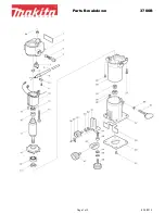
3700B
Brand: Makita Pages: 2

A 240 Combo
Brand: Olympia Pages: 75
DWE6000
Brand: DeWalt Pages: 56

BA-FS27
Brand: Banner American Pages: 14

DR-L4
Brand: 123inkt Pages: 74

BSN20892
Brand: Business Source Pages: 10

ULTIMA 65-1
Brand: GBC Pages: 75

Orca 1600
Brand: GBC Pages: 95

OORCA-III
Brand: GBC Pages: 109

Spectra 95
Brand: Fellowes Pages: 14

fusion 1100L
Brand: GBC Pages: 76

HeatSeal Creative
Brand: GBC Pages: 7

KF14659
Brand: Q-Connect Pages: 18

KF14657
Brand: Q-Connect Pages: 21

HeatSeal H65
Brand: GBC Pages: 15

SIGN
Brand: Easymount Pages: 11

Catena 105
Brand: GBC Pages: 12

PROMASK 27
Brand: usi Pages: 6


