Fehler! Verwenden Sie die Registerkarte 'Start', um Name dem Text zuzuweisen, der hier angezeigt werden soll.Fehler! Verwenden Sie die
Registerkarte 'Start', um Name dem Text zuzuweisen, der hier angezeigt werden soll.Fehler! Verwenden Sie die Registerkarte 'Start', um
Name dem Text zuzuweisen, der hier angezeigt werden soll.
MGH
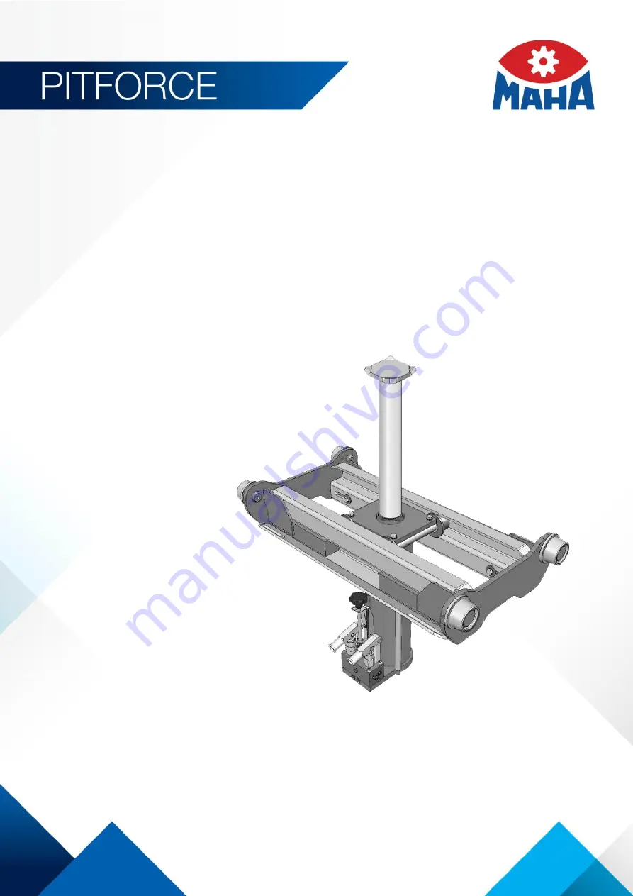
Pit Jack
Original Operating Instructions
BA550401-en
MGH 5.5/75
MGH 5.5/45
MGH 11.0/75
MGH 11.0/45
MGH 14.5/75
MGH 14.5/45
MGH 16.5/75
MGH 20.0/75
MGH 30.0/75
MGH 5.5 PD
MGH 14.5 PD