Magnetrol Pulsar R86, Инструкция по установке и эксплуатации
Magnetrol Pulsar R86 - инновационный уровнемер с максимальной точностью и надежностью. У нас вы можете скачать бесплатное руководство пользователя для Magnetrol Pulsar R86. Посетите manualshive.com, чтобы загрузить свой экземпляр руководства прямо сейчас.
Поделиться
Скачать


Отзывы:
Нет отзывов
Похожие инструкции для Pulsar R86

DR5BT
Бренд: Hama Страницы: 14

CB1-DAB-BLK
Бренд: MAJORITY Страницы: 20
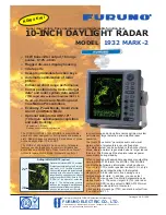
1932 MARK-2
Бренд: Furuno Страницы: 2

AX/16X
Бренд: Dongguan Wanma Electronic Страницы: 10

airMAX Bullet Titanium BM2-Ti
Бренд: Ubiquiti Страницы: 24

DOMINO 105 Series
Бренд: 4 tec SENSORTECHNOLOGY Страницы: 3

SpeedNet SDR
Бренд: S&C Страницы: 4

XBee RR
Бренд: Digi Страницы: 67

RK5640
Бренд: ROAD KING Страницы: 18

EP5500
Бренд: Excera Страницы: 9

VP388T
Бренд: Spedal Страницы: 13

VX328
Бренд: Velex Страницы: 11

OV-CB-501B
Бренд: Overmax Страницы: 43

HRA-590D+
Бренд: Roadstar Страницы: 35

Link-9
Бренд: Lowrance Страницы: 74

SP-1940
Бренд: Panacom Страницы: 16

00054242
Бренд: Hama Страницы: 86

SAL BT WORK
Бренд: Somogyi Elektronic Страницы: 27


