Subwoofer
Model: LS-SUB-100
1
Dear Customer,
CONGRATULATIONS. The LS-SUB-100 Powered Subwoofer, when used as
described, will give you years of dependable service. We have taken numerous
measures in quality control to ensure that your product arrives in top condition,
and will perform to your satisfaction. In the rare event that your LS-SUB-100
Powered Subwoofer contains a damaged or missing item, does not perform as
specified, requires warranty service or you have an installation problem,
please call our TOLL FREE number US 800-638-3600 and ask to speak with a
member of our technical service team, or submit your questions by E-Mail to
[email protected] and a member of our technical service team will
respond by E-Mail to your questions.
Location
Place the powered subwoofer in a
location that allows air to circulate
around it. Amplifier location and
installation will vary from application
to application. Carefully consider as
many installation locations and
configurations as is practically
possible. DO NOT COVER the
powered subwoofer with carpet or
enclose it behind interior panels.
DO NOT mount inverted or upside
down. The amplifier may be
mounted vertically.
Connect the fused 12 Volt DC
power wire, chassis ground cable,
and remote wires. (SEE SECTION 3,
ELECTRICAL CONNECTIONS)
Turn on the car stereo. If the Power
Protection light is green, turn off the
stereo and proceed to the next
section. If the Power Protection light
is red, review all of the connections
and wires. You may have a loose
connection, a bad chassis ground, or
an inadequate size power wire. If the
problem persists after reviewing all
of the connections and wires, call
our toll-free help line for assistance.
Do not mount inverted or
upside down. Do not cover
with carpeting or enclose it
behind interior panels.
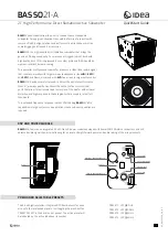
Features & Functions
®
BATTERY AND GROUND WIRES MUST BE
#10AWG FOR PROPER PERFORMANCE
1. Pre-installation
Specifications
• 400 Watts Total Power
• 100 Watts @ 4 Ohms < or = 1% THD+N.
S/N> or = 75 dbA ref. 1 Watt Output @ 14.4 VDC.
• Measured at 14.4 VDC Input Voltage
• Frequency Response: 25~150 Hz
• Dimensions: 19.63” L X 9.25” W X 7.25” H
• Ported ABS Enclosure
• 8” Subwoofer
• Fuse: 20 Amp Automotive Blade Type
Water Damage: Do not install this Powered Subwoofer in a
location that will expose it to water or moisture.
Dust or Dirt: Do not install this Powered Subwoofer in a location
that will expose it to dusty or dirty conditions.
DO NOT BLOCK THE PORT OPENING FOR ANY REASON.
Modifications: Do not open the Powered Subwoofer for any reason, or modify
it in any way. If modified in any way a fire hazard or malfunction may occur.
Modification will void the warranty.
Steel / Wood Mount
With a hammer & nail set/center
punch, make dimple marks on the
surface for each mounting screw.
(FIG. 2)
Drill 4 pilot holes with an electric
drill & 1/16” bit. Make sure that
nothing is behind the mounting
surface that can be damaged
when drilling.
(FIG. 4)
When mounting the Powered Subwoofer, make sure there is enough
room for access to make adjustments to the volume control.
(#10 AWG minimum wire size)
(#10 AWG minimum wire size)
2. Mounting the Powered Subwoofer
Read the following wiring instructions very carefully. If you have any
trouble understanding any of these instructions, have the amplifier
professionally installed by an experienced technician. Incorrect wiring
will prevent the amplifier from operating, or will damage the amplifier.
3. Electrical Connections
STEP 1.
STEP 2.
STEP 3.
STEP 4 .
Attach the supplied brackets to the base of the Powered Subwoofer
using the 4 Phillips Pan Head Screws.
(FIG. 1)
1. Power Terminal
1.
Strip 1/2” of insulation from the end of the minimum 10 gauge power
wire. Connect the 10 gauge power wire to the battery terminal for the
LS-SUB-100.
2.
Loosen screw to open battery and ground connector plates on
rear of amplifier.
3.
Insert the 10 gauge wire between the connector plates. Turn screw until
power cable is tight.
2. Remote Terminal
The REMOTE wire connection automatically turns on your amplifier when
your stereo is tuned on. On most stereos, this wire is marked as the
REMOTE, ACCESSORY, or POWER ANTENNA.
1.
Locate the REMOTE, ACCESSORY, or POWER ANTENNA on the stereo.
(Refer to you stereo owner’s manual.)
2.
Splice the REMOTE, ACCESSORY or POWER ANTENNA wire from rear of
the stereo to a length of wire that will reach the rear of the amplifier.
3.
Loosen screw and open REMOTE connector plates on rear of amplifier.
4.
Insert wire end between the REMOTE connector plates.
5.
Tighten screw closing REMOTE connector plates on wire.
3. Ground Terminal
1.
The ground connection cable should be attached to clean, unpainted
chassis metal for a good electrical connection.
2.
Find good, no-rusted chassis metal, as close to the amplifier as possible.
3.
Drill a pilot hole with a 1/16” drill bit.
4.
Use sandpaper to expose an area of bare metal around the pilot hole
about the size of a dime.
5.
Tightly fasten the provided ground cable with self tapping sheet metal
screw to the chassis metal. A loose ground will cause distortion and
popping noises in the speakers.
Carpet Mount
Cut a piece of plywood 22” x 11”
and slide it under the carpet where
the Powered Subwoofer will be
mounted and proceed to step #4.
(FIG. 3)
FUSE 20A
GND
REM
BA
TT
LINE INPUT
L
R
MIN MAX
VOLUME
LS-SUB-100