background image

Issue 2 

    10/12/2010 

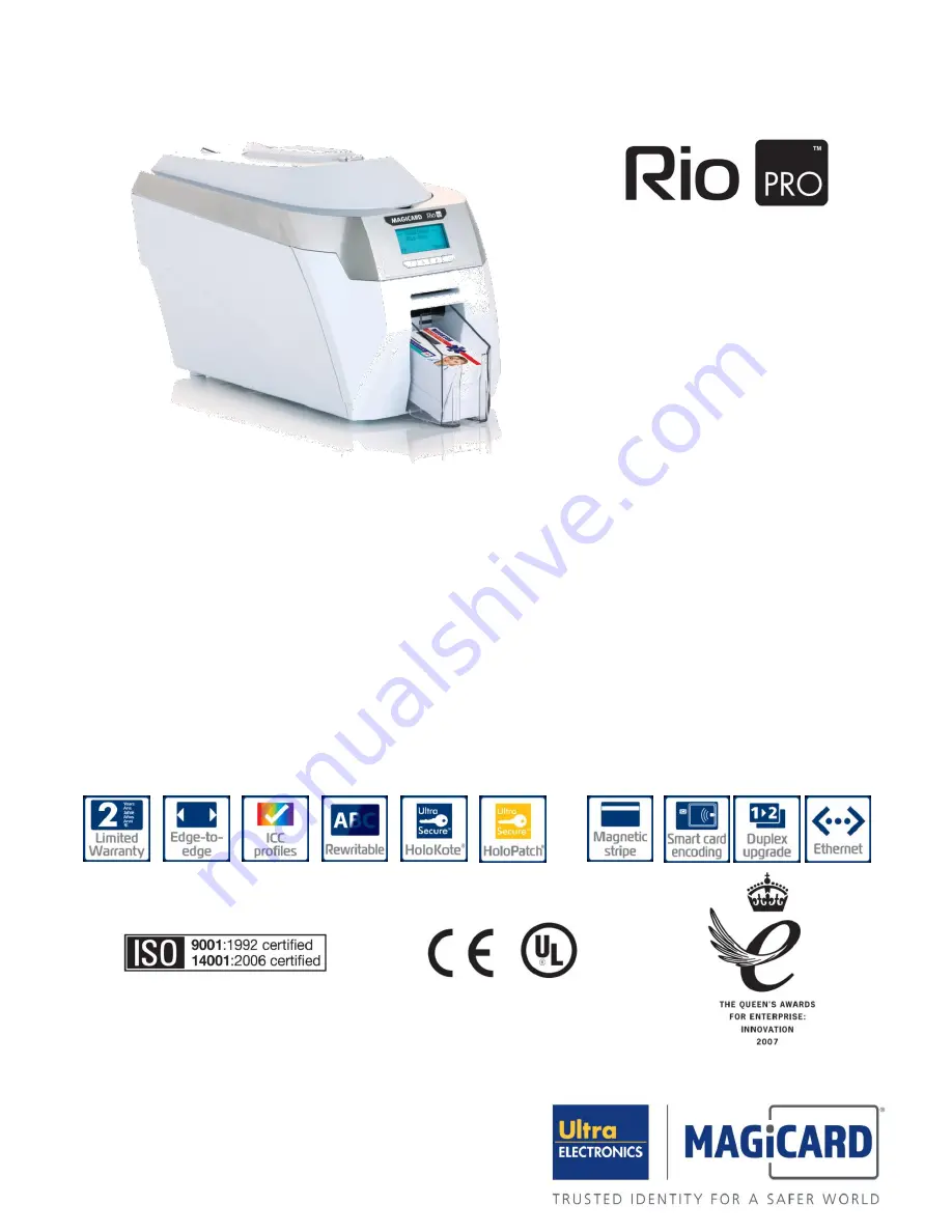
Colour ID Card Printer MAGICARD

®

 Rio Pro Maintenance Manual 


Ultra Electronics Card Systems 
 
www.magicard.com 


Magicard Rio Pro single sided colour ID Card Printer  


3633-9001 

Magicard Rio Pro Duo double sided colour ID Card Printer 


3633-9021 

 
Magicard Rio Pro Mag single sided colour ID Card Printer 


3652-9002 

Magicard Rio Pro Duo Mag double sided colour ID Card Printer 


3652-9022 

 
Magicard Rio Pro single sided colour ID Card Printer with Smart Encoder 


3652-9005 

Magicard Rio Pro Duo double sided colour ID Card Printer with Smart Encoder 


3652-9025 

 
Magicard Rio Pro Mag single sided colour ID Card Printer with Smart Encoder 


3652-9006 

Magicard Rio Pro Duo Mag double sided colour ID Card Printer with Smart Encoder  

3652-9026 

 
Duplex Upgrade Kit 


3633-0052 


Standard 

Option 

Option 

Standard 

Standard 

Standard 

Standard 

Standard 

Option 

Option 

Summary of Contents for Rio Pro

Page 1: ...Magicard Rio Pro Duo Mag double sided colour ID Card Printer 3652 9022 Magicard Rio Pro single sided colour ID Card Printer with Smart Encoder 3652 9005 Magicard Rio Pro Duo double sided colour ID Card Printer with Smart Encoder 3652 9025 Magicard Rio Pro Mag single sided colour ID Card Printer with Smart Encoder 3652 9006 Magicard Rio Pro Duo Mag double sided colour ID Card Printer with Smart Enc...

Page 2: ...n 8 4 driver description 31 Section 9 PRINTER DISPLAY 32 section 9 1 menu options 32 section 9 1 1 1 clean rollers 33 section 9 1 2 2 test card 33 section 9 1 3 3 info 34 section 9 1 4 4 hand feed 34 section 9 1 5 5 mag self test 35 section 9 1 6 6 reset printer 35 section 9 2 maintenance mode 36 section 9 2 1 soak test mode 36 section 9 2 2 Sensor test Mode 37 section 9 2 3 previous menu 38 secti...

Page 3: ... Error code list cont 65 Section 14 MAGICARD PRINTER SUPPORT UTILITY 79 section 15 MAGNETIC ENCODING 88 section 15 1 magnetic encoding standards 88 SECTION 15 2 BASIC MAGNETIC ENCODING 90 SECTION 15 3 ENCODING USING BADGE PRINTING SOFTWARE 91 section 15 4 ASCII Character Set supported by the Rio Pro 92 section 15 5 iso standards 92 section 15 6 error checking 93 section 15 7 FITMENTS to the printe...

Page 4: ...ith the furnishing performance or use of this material This document contains proprietary information belonging to Ultra Electronics Limited and may not be wholly or partially copied stored in a data retrieval system disclosed to third parties or used for any purpose other than that for which it was supplied without the express written authority of Ultra Electronics Limited All rights are reserved...

Page 5: ...tallation mit einem 16 A Überstromschalter abgesichert ist When Handling the Printer Avoid touching the thermal printing edge of the Print Head Any grease and contamination will shorten its life Before transporting the Printer remove the dye film and Card Hoppers and pack the Printer in its original packaging Location Requirements for your Printer A clean dry level surface Cable access at the rear...

Page 6: ...Holokote security watermark Dye Sublimation Inkjet Printing There are two factors that contribute to the quality of Dye Sublimation Printers The first is continuous tone and the other is un dithered colour In Dye Sublimation printing colours are not laid down as individual dots as is done in inkjet Printers The colour produced by a dye sub is the result of the mixing of pigments to get the actual ...

Page 7: ...d being rigid the quality of the Card surface is extremely important if high quality images are to be produced Cards should be selected which are cut cleanly at the edges and have perfectly flat surfaces There are various Card manufacturers and several different types of PVC Card Each of these will accept colour in differing amounts using the same Print Head temperature This is due to the PVC bein...

Page 8: ... the Print Head temperature to stop the colours getting darker along the length of the Card This is set up in the mid range of the print density and will be slightly different on dark or light colours Plain colour areas are the most likely to show any variation so it is better to use textured colours where possible If a coloured band runs along the Card and into a picture it will affect the area o...

Page 9: ... fault display Print Head cooling Fan allowing the printer to Print continuously Automatic adjustment for different Card thicknesses Smart Attractive compact design Intuitive LCD with simple button menu selections USB and Ethernet Interface Microsoft Certified plug and play Driver make the Rio Pro easy to install and use Secure Magicard Rio Pro features the patented Holokote watermark technology H...

Page 10: ... 5 5 kilograms 12 lbs including Hoppers and PSU Dimensions 453mm L x 206mm W x 233mm H incl Hopper and Stacker 17 8 L x 8 1 W x 9 2 H Dye film loading Drop in Dye Film design Dye film Set up Automatically detects Dye Films Software Supplied with Windows 2000 2003 Server XP Vista and Win 7 Drivers Magstripe Encoder Optional HICO LOCO magnetic stripe encoder to ISO 7811 standard Card Size Standard I...

Page 11: ... Maintenance Manual 11 SECTION 3 COMPONENT LAYOUT Cleaning Roller Blank Card Hopper Print Head Assembly Top Cover Opening Latch Front Card Stacker LCD Display Hand Feed Slot Rear Card Hopper DC Power Input Network Connection USB Connection ...

Page 12: ...ssembly Rear Card Hopper LCD Display Hand Feed Entry Exit Slot Front Card Stacker Function Buttons Dye Film Sensor Bracket top Rio Pro component layout viewed from front of Printer Card rotation Unit Top Cover Interlock Sensor Unused Dye Film Spool Holder Automatic Card Adjustment Thermal Print Head HoloKote Flex Key Slot ...

Page 13: ...r Flipper Unit Card Drive Roller Cleaning Roller Rear Idle Roller Print Head Roller Flipper Mechanism Rotation Motor Flipper Mechanism Direction Motor Dye Film Drive Motor Card Feed Motor Main Stpper Motor Cam Motor Rio Pro Motors viewed from underside of Printer Rio Pro component layout viewed from top of Printer ...

Page 14: ...ow is a guide to selecting the best Dye Film to use for any intended application Ribbon Layout Colour Key Included with each Dye Film is a Cleaning Roller Full color Cards or monochrome Cards Per ribbon Ribbon Panel layout Part Number Full Colour 300 one side only or 150 both sides YMCKO MA300YMCKO Monochrome Black Red Blue Green Gold Silver White Scratch 1000 one side only or 500 both sides K MA1...

Page 15: ...number of prints If it fails to read any of the data from the RFID protective Tag the Printer assumes it has single colour Film fitted Operate the top cover release catch and lift the cover Place the cassette into the 4 cradles right side first and press it into place Ensure the gear front right engages with the Spool Gently close the top cover until it clicks into the closed position The Printer ...

Page 16: ... printing For good consistent results stick to a single variety of good quality Cards such as those available from your Magicard Dealer Card Size Card Thickness Minimum 0 51mm 0 020 Standard 0 76mm 0 030 Maximum 1 02mm 0 040 To obtain good quality prints the Cards must be Glossy white Free from dirt or grease Free from surface contamination e g finger marks Free from burrs at the edge of the Card ...

Page 17: ...in the Printer These problems range from poor image quality failure to feed from the Card Hopper and Dye Film being cut through to Cards getting jammed in the roller mechanism Contact Chip Cards Smart Cards must conform to the ISO 7816 specification with the Chip contacts being below the surface of the Card It is unwise to print graphics or text directly adjacent to the Smart Chip as image quality...

Page 18: ...for this upgrade Simply drop the Dye Film upgrade into the machine 1 Purchase the upgrade kit from Magicard Sales 2 Fit the upgrade Film into the Printer 3 Close the Lid and connect power to the machine 4 Wait for the Printer to finish initialising the Printer Display will change colour and show text You are now ready to print The upgrade is Printer specific so once the Dye Film upgrade has been f...

Page 19: ...vice Agent to identify any module or component that has failed replace it and carry out the appropriate setting up and testing to ensure satisfactory operation Feedback Ultra Electronics Limited is committed to the manufacture of quality products and encourages feedback of any problem or faults occurring in the field in order that we can improve the quality of our design manufacture and support We...

Page 20: ...e Ultra will at its discretion repair or replace the defective parts at no charge to the Customer Warranty Limitations The warranty does not apply to MAGICARD Printers that have been Damaged through physical or electrical mishandling Damaged through operation in environments that are outside normal office conditions in terms of corrosive atmosphere temperature humidity shock or vibration Improperl...

Page 21: ...ns may not apply to all Customers For warranty enquiries please call or fax our Customer Support Manager Ultra Electronics Limited MAGICARD Service Centre Waverley House Hampshire Road Granby Estate WEYMOUTH Dorset DT4 9XD U K Tel 44 0 1305 784738 Fax 44 0 1305 777904 SECTION 6 3 INTERNET SUPPORT To further enhance the support already available to Magicard Customers the Magicard Web site contains ...

Page 22: ...Cleaning Kit see the Cleaning Supplies Section 7 2 A clean Printer produces better quality Cards as dust and dirt are not present when the Card is being printed A clean Printer is far less likely to require factory maintenance and the Print Head in your Printer will last for many years of normal use Remember large particles of dirt can damage the Print Head Magnetic Encoding degrades when rollers ...

Page 23: ... press Ok and follow the on screen instructions 2 Remove the Cards lift out the rear feed Hopper and then press Next And Remove film open the lid and lift out the Dye Film Leave the Lid open and press Next 3 Ready to clean Take a new Cleaning Card from its packaging and then press Yes 4 Insert Cleaning Card into slot when prompted place the narrow end of the Cleaning Card into the front Card feede...

Page 24: ...lm is fitted 1 Open the Printer lid and remove the used Dye Film Pull out the used cleaning spool 2 Remove the central roller bar 3 Slide the central roller bar through the middle of the new cleaning roller 4 Carefully remove the protective layer to reveal the sticky surface 5 Place the new cleaning roller into the Printer Please Note If the steel shaft from the cleaning Roller becomes lost a repl...

Page 25: ...s also a good idea to clean the Print Head when you replace the ribbon 1 Use the special Print Head cleaning Pen from your Magicard printer cleaning kit See Section 6 1 Cleaning Supplies 2 Open the Printer and draw the Pen several times across the complete length of the Print Head Please Note The Print Head becomes hot during printing so the Cleaning Pen may need to be drawn along the face of the ...

Page 26: ...lowing Operating Systems only Windows 2000 Windows XP Windows 2003 Server Windows Vista 32 and 64 bit Windows 7 32 and 64 bit SECTION 8 1 INSTALLATION INSTRUCTIONS FOR WINDOWS 2000 XP 2003 SERVER VISTA Load the Driver CD ROM into the PC you have connected to the Printer If the CD does not run automatically click the Start Button then click on run Type D autorun where D is the drive letter for your...

Page 27: ...Ultra Electronics Card Systems Rio Pro Maintenance Manual 27 ...

Page 28: ... are that the computer does not seem to detect the Printer s USB connection and the Test Page fails to print Recover the file as follows Navigate to c windows inf Windows XP or c winnt inf Windows 2000 Find the file named usbprint in and then rename it to usbprint inf Reconnect the USB cable SECTION 8 1 INSTALLATION INSTRUCTIONS FOR WINDOWS 2000 XP 2003 SERVER VISTA AND WINDOWS 7 CONTINUED Ensure ...

Page 29: ... DRIVER FOR WINDOWS 2000 XP 2003 SERVER On the PC go to Start Control Panel Then select Add or Remove Programs Classic view Category view Select the Magicard RIO Pro entry and click on Change Remove Choose the Magicard RIO Pro you wish to remove there may be more than one and click Next Lastly follow the on screen prompts or ...

Page 30: ...followed by Control Panel Category View choose Uninstall a program Classic View choose Program and Features Select the Magicard Rio Pro Printer and the choose the Uninstall Change Button Follow the instructions on the screen Ensure the Printer is disconnected SECTION 8 3 UN INSTALLING THE DRIVER FOR WINDOWS VISTA WINDOWS 7 ...

Page 31: ...ing each individual Printer Driver setting The Printer Driver contains a built in help file in HTML format this file gives an excellent clear explanation of each Driver setting To view the Driver s help file go to the Printer Preferences as described above and click on the Help Button in any of the Tabs ...

Page 32: ...on SECTION 9 1 MENU OPTIONS Press the Menu button The first menu option will be displayed Press the button where indicated to step through each option in the menu The following menu options will be displayed 1 of 6 Clean rollers 2 of 6 Test card 3 of 6 Info 4 of 6 Hand feed 5 of 6 Mag self test 6 of 6 Reset printer Options 1 6 are explained on Page 32 Off Button Switches the Printer off To switch ...

Page 33: ...ean the Printer using a Cleaning Card each time the Dye Film roll is replaced SECTION 9 1 2 2 TEST CARD Follow the procedure below to clean the Card transport rollers in the Printer Having selected this option you will be asked to confirm that you wish to print a Test Card If you select Yes the Printer will feed a Card from the Hopper and print an internally generated Test image on it ...

Page 34: ...r or Hand Feed front slot OFF This is the default setting Cards will be fed automatically from the Card Hopper ON At the start of each print the Printer will request you to feed a Card through the Card Feed slot in the front of the Printer NOTE Cards will NOT feed from the Card Hopper Once the desired mode is selected press the SAVE Button Step into each option using the right most arrow button Us...

Page 35: ...ES option arrowed the Printer will feed a Card from the Hopper encode the magnetic stripe and print an internally generated test image on it NOTE If your Printer does NOT have a magnetic encoder fitted it will be unable to perform this test and will instead display the message Mag not fitted SECTION 9 1 6 6 RESET PRINTER Selecting this option Yes will force the Printer to re initialise the same ef...

Page 36: ...k the functionality of the Printer Each electronic Sensor can be checked individually Image Start End positions and the Dye Film sensing system can be calibrated It is accessed by opening the Lid and holding down the Menu Button for 3 seconds SECTION 9 2 1 SOAK TEST MODE CAUTION Do not fit Dye Film into the Printer during the Soak Test mode The Dye Film motor is advanced during the cycle The Dye F...

Page 37: ...ostic Tool when Sensors in the Printer may be suspect During the Cam Sensor test the value above will toggle between X and 0 The colour of the Printer s Display will change to purple The values shown above are those measured by the Dye Film Sensor for each Film Panel The colour of the Printer s Display will change to purple Each of the above letters represents a Sensor or Button within the Printer...

Page 38: ...Ultra Electronics Card Systems Rio Pro Maintenance Manual 38 SECTION 9 2 3 PREVIOUS MENU Exit out of the Maintenance Menu ...

Page 39: ...Print Head in the Rio Pro Rio Pro Duo Printer SECTION 10 1 PRINT HEAD DAMAGE Dust or contamination on the Card or Dye Film is dragged below the Print Head This causes scratches and permanently damages the printing surface contaminant such as sand Print direction The contaminant imbeds into the PVC surface and is dragged into the print head Card Dye Film Print Head ...

Page 40: ... 2 PRINT HEAD ELECTRONIC FAILURE If an internal electronic component has failed inside the Print Head this causes the printing elements to switch on or off continuously The Cards below show examples of electronic failure The Cards below show examples of electronic failure ...

Page 41: ...h Electrostatic Sensitive Devices All precautions for handling Electrostatic Sensitive Devices should be followed at all times including the use of a grounded wrist strap Start Switch the Printer Off Remove Connector Push backwards then tilt upward 1 2 Fit the new Print Head 1 2 Re connect the new Print Head Press any Button to switch the Printer On 2 ...

Page 42: ...TY CALIBRATION CAUTION The Print Head Density Programmer PDP is calibrated to suit the Print Head that it is supplied with It will not be suitable for any other Print Heads and therefore should only be used for a specific Print Head Assembly 1 Open the Printer Lid Close the Printer Lid Press any Button to switch the Printer On Finished ...

Page 43: ...f the Card is the edge that ejects out of the Printer first Print Head Angle too positive Rear end of the Card will show wrinkling or Dye Film overheating The rear of the Card is the edge that ejects out of the Printer last Section 10 5 Print head setup and adjustment The best type of image for ensuring the Print Head angle is setup at its optimum position is a mid grey Card R 128 G 128 and B 128 ...

Page 44: ... the front end of the Printer out of the case tilting it backwards This will then release the two rear plastic catches and allow the complete print engine to be removed Refitting is the reverse sequence Locate the connector panel and carefully line up the two rear plastic catches first and lower the print engine into place The front catches will locate and click into place ensure no wires are trap...

Page 45: ...he reverse procedure Removal Refitting of the Lower Dye Film Sensor 1 Gently pull upwards the plastic cross piece that encloses the lower Dye Film Sensor in place it is clipped into the plastic Side Plates 2 Turn the plastic cross piece over and disconnect the Sensor cable from the small PCB 3 Sensor PCB can now be unclipped from the plastic cross piece Refitting is the reverse procedure ensuring ...

Page 46: ...ures involve contact with Electrostatic Sensitive Devices All precautions for handling Electrostatic Sensitive Devices should be followed at all times including the use of a grounded wrist strap Removal Refitting the Controller PCB 1 Disconnect all the wiring from around the outside edge of the Controller PCB Take care not to damage the small PCB connctors 2 Unclip the four plastic catches and rem...

Page 47: ...in print engine Refitting is the reverse procedure SECTION 11 6 REMOVING REFITTING OF THE FRONT REAR CARD SENSOR SECTION 11 7 REMOVING REFITTING THE LCD DISPLAY Removal Refitting of the Front Rear Card Sensor 1 Working inside the printing compartment the front and rear Card Sensor plastic clips can be released The plastic clips are situated adjacent to the Card path at the front and rear of the pr...

Page 48: ...ect position Refitting is the reverse procedure 2 Drive Belt can be removed by sliding it off the outside of the Cam Shaft Pulley Refitting is the reverse procedure 3 Small Pulley can pulled from the DC Cam Motor shaft Refitting is the reverse procedure but a new Pulley is essential unless glued into position Tacho and Sensor System 1 Carefully withdraw the Tacho Wheel plastic cover from the side ...

Page 49: ... used 3 Idle tension roller pressure can be released then the large drive Belt removed Note how the belt is fitted and which Pulleys it fits around Refitting is the reverse procedure then release the idle roller to tension the Belt 4 The individual roller drive Pulleys can now be removed by either depressing the retaining tabs on the shafts or releasing the spring washers Slide the Pulleys outward...

Page 50: ...tor 2 The motor is held in place by two screws through elongated holes The elongated holes provide movement for Belt tension Remove these screws 3 Remove the motor out through the bottom of the print engine Refitting is the reverse procedure but leave the screws loose until the main drive Belt is fitted and tensioned Card Feed Motor 1 Disconnect the motor connections 2 The motor is held in place b...

Page 51: ... complete chassis cover upwards away from the print engine 4 Remove the wire loom from the left hand side of the Printer note it s route through the chassis Refitting is the reverse procedure ensuring no wires are trapped and the Lid opens and closes freely SECTION 11 11 REMOVAL OF THE CHASSIS COVER The Chassis cover can be removed from the main print engine however there are no user replaceable p...

Page 52: ...procedure drop the rotation unit into position ensuring the correct orientation and then fit the Bearing Plates Removing the Idle Rollers 1 Remove the Idle Link Plate springs located centrally above the Idle Link Plate from each side of the print engine 2 Lift and withdraw the left and right Idle Link Plate from each side of the Printer 3 Remove the Idle Rollers from inside the Printer Refitting i...

Page 53: ...unting of the Large Bearing Plate When Removing and refitting these always wear approved eye protection Removing the Large Bearing Plates 1 Ensure all remaining Spring Washers are removed for the metal roller shafts 2 Working underneath the printer release the four left and right plastic catches holding the bearing plates in position Refitting is the reverse procedure ensuring Cam and roller shaft...

Page 54: ...on when refitting Refitting is the reverse procedure ensuring the Cam linkage is correctly orientated Removal Refitting of the Card Guide 1 Remove the two return springs from either end of the Card guide Parts of the springs are inside the Card guide plastic assembly 2 The guide will be loose push it against the internal side wall and lift up out of the machine Refitting is the reverse procedure l...

Page 55: ...ated so it is aligned with the Card feed mechanism 3 Trapped Card is ejected out the front of the Printer Printer Ready Possible Errors 1 Nothing Happens Check external Power Supply connection into the back of the Printer Is the green indicator on the external PSU on 2 LCD is on but information corrupted Microprocessor has failed to start replace controller PCB 3 Lid Open Error When the lid Sensor...

Page 56: ...Cards are jamming in the Flipper Unit 1 Drive pulley or Belt has become detached 2 Sensor is not positioning the Rotation Unit 3 Early Firmware version 1 Ensure the Flipper Unit components are fitted correctly 2 Ensure the rotation position Sensor is connected and functioning correctly 3 Ensure the Printer has the latest Firmware installed 1 Section 11 8 2 Section 9 2 2 11 8 3 Section 18 Error Can...

Page 57: ... colour can be in any position on the Card 1 Dust dirt or surface contamination on the Card 2 Dust dirt or contamination on the Dye Film 1 Ensure the Cards are flat clean and free from contamination or fingerprints replace if necessary 2 If the ribbon has to be removed avoid touching it and do not place flat on the surface static 3 Replace the Sticky Roller inside the Printer one is included with ...

Page 58: ...ion Usually a fault with either the Print Head or Controller PCB 1 Replace Print Head 2 Replace Controller PCB call Magicard Technical Support 1 Section 10 2 Section 6 1 Light faded edge along the length of the Card 1 Raised area or burr along the same edge to the Card 2 Poor contact between the Print Head printing surface and the Card 1 Flip the Card over and print on the reverse if applicable ot...

Page 59: ... and disappears immediately 1 Incorrect Port selected in the Driver settings 2 Corrupted Printer Driver 1 USB printing Port should be selected to USB001 2 Remove the current Driver and re install the latest version Unable to open the Printer settings within Printers and Faxes 1 Corrupted Printer Driver 1 Remove the current Driver and re install the latest version After installing the Driver and co...

Page 60: ...Ultra Electronics Card Systems Rio Pro Maintenance Manual 60 ...

Page 61: ...d off 2 Magnetic Encoded data is in the wrong place on the Magnetic Stripe 3 Magnetic Encoded data is not the correct format for the swipe Reader to understand 4 Magnetic Encoding Head is either mis aligned or faulty 1 Position the Card in the Hopper with the magnetic stripe underneath and to the left side of the Printer Ensure Magnetic Verification is switched on in the Printer Driver 2 Clean the...

Page 62: ...be either during printing or initialisation 01 07 Error is shown if the Lid is opened while aligning the start of a coloured Dye panel with the edge of the Print Head prior to printing 01 08 Error is shown if the Lid is opened when the print job is being validated against the parameters in the Printer Driver This can also happen if a print job is sent to the Printer while the Lid is open 01 09 Err...

Page 63: ...nto the print engine module If the front Sensor remains unblocked for more than 3 seconds it assumes a Card is trapped in the Flipper mechanism 04 04 Error can occur while moving a Card from the print engine module to the Flipper mechanism If the front Sensor remains blocked for more than 5 seconds it assumes a Card is trapped in the Flipper mechanism The Flipper will try to intialise but the Flip...

Page 64: ...e Card has already moved forwards to block the front Card Sensor 04 11 Error is shown while trying to eject the Card out of the Printer If the front Sensor remains blocked for more than 3 seconds the error is seen At this stage the Card has already moved towards the Flipper mechanism and has blocked the front Sensor 04 12 This error is raised if the Flip Sensor is always blocked after smart encodi...

Page 65: ...ddle Card Sensor from in the rear Card Sensor It occurs if the rear Sensor is not unblocked within 3 seconds 06 07 This error can occur while trying to hand feed a Card to the standby position over the middle Card Sensor If we fail to see the mid Sensor block within 5 seconds the error will be seen Note by this point a Card has already been seen in the front Sensor block and then unblock 06 08 Err...

Page 66: ...s displayed 06 14 Error can be shown during the magnetic encoding cycle If a Card fails to unblock the rear Card Sensor within 4 seconds the error is displayed At this point the Card is already in the magnetic encoding standby position and has begun to move the Card forwards towards the magnetic encoding Head 06 15 Error is shown while moving the Card forward towards the front Sensor during the so...

Page 67: ... only displayed when the Tag is detected but invalid Error Number Displayed Error Error Code Description of Problem 08 Out of Dye Film Please load a new roll of Film to continue 08 00 Error is shown while trying to advance the Film to the start of the next panel If no Tacho Sensor pulses or Dye Sensor transitions are seen for at least 5 seconds the error is displayed 08 01 Error is shown while try...

Page 68: ...n while trying to advance the Dye Film to the start of the next colour panel If Dye Film Sensor transitions are seen but no Tacho pulses occur for at least 5 seconds the error will be displayed 08 11 Error can be shown while trying to advance the Film to the start of the next colour panel If Tacho and Dye Film sensor transitions are seen but the Dye Film Sensor change does not stabilize within 5 s...

Page 69: ...y type Film if the image cannot be printed using the loaded Film this particular error will be displayed This particular error may arise if the user manages to send a print job file requiring either colour or Overcoat to a machine which has single colour only Film fitted 10 03 Error can be shown while determining the print cycle sequence for the current print job using black and Overcoat type Film...

Page 70: ...r often indicates that either the Dye Film LED is poorly positioned or that the Dye Film LED needs to be calibrated using the FCL command This error is similar to 11 00 but the surrounding context is slightly different 11 00 can occur whenever the Film position is being set whereas 11 01 can only occur when the Film position is being set and the Printer has had to recover from a Dye Film panel mis...

Page 71: ...Error is shown while trying to lift the Print Head If the Cam Sensor does not block within 5 seconds an error is displayed Note this function is only used by the HEAD quick command and the Cleaning Routine 16 03 Error is shown while trying to lift the Head at the end of printing a panel If the Cam Sensor does not clear within 5 seconds the error is shown By this point the Sensor has already been b...

Page 72: ...Ultra Electronics Card Systems Rio Pro Maintenance Manual 72 ...

Page 73: ...el Error Number Displayed Error Error Code Description of Problem 18 Flipper Error cannot initialise the Flipper Please clear Printer mechanism 18 00 Error is shown while trying to initialise the Flipper mechanism If the Flipper Position Sensor is not blocked within 4 seconds the error is displayed By this point the Printer has already cleared any Card jam away from the Flipper mechanism if the fr...

Page 74: ...ting has been requested for the back of the Card but the Printer does not support colour printing the error is displayed Note that this type of Printer does not yet exist and this feature is reserved for future development Error Number Displayed Error Error Code Description of Problem 21 CLEAN REQUIRED Please clean the Rollers to avoid deterioration 21 00 Error can be shown if the cleaning prompt ...

Page 75: ...Ultra Electronics Card Systems Rio Pro Maintenance Manual 75 22 04 Error is shown after completing a Sensor Test initiated using a SNS command If the Flip Sensor result is Invalid the error is displayed ...

Page 76: ... RFID Tag this error will be displayed 24 04 Error is shown while trying to feed a Card from the Hopper to the printing area If the Printer sees the middle Card Sensor block before the rear Card Sensor does the error is displayed This could possibly indicate that the rear Sensor has dropped out of position but could also mean that the middle Card Sensor is faulty 24 05 Error is shown while trying ...

Page 77: ...nting area If the Printer sees the rear Card Sensor block before the front or middle Card Sensor the error is displayed This could possibly indicate that the front Card Sensor has failed that the middle Card Sensor has dropped out of position or that the rear Sensor is faulty 24 11 Error is shown while trying to hand feed a Card into the printing area If the Printer sees the rear Card Sensor block...

Page 78: ...Ultra Electronics Card Systems Rio Pro Maintenance Manual 78 SECTION 13 ERROR CODE LIST CONT Error Number Displayed Error Error Code Description of Problem 26 27 28 29 30 31 32 33 34 35 ...

Page 79: ... and configuration tools for use when setting up and testing Magicard Printers Install the Magicard Support Utility from the Driver CD Alternatively it can be found in Program Files in a folder called Ultra Electronics Ltd It is also available from our website using the following link http www Magicard com support technical support R L id lang 1 printerID 39 supportOption 3 Once installed a short ...

Page 80: ... the number makes the image length longer closer to the rear of the Card thus decreasing the width of the white line at the rear of the Card A numerical change of 1 moves the end position a distance of 1 pixel width Print Head Density Every Print Head has a different resistance which means they will print at different colour depths To ensure each Rio Pro will print at a calibrated density the adju...

Page 81: ... image parameters cannot be modified After entering Dealer Mode the LCD backlight becomes yellow The image parameters may be modified within the permitted limits shown in the table below If the entered values are outside of the permitted limits they will be reduced to the upper or lower limit as appropriate After leaving Dealer Mode the LCD backlight returns to it s normal colour The image paramet...

Page 82: ...ng Unit If the parameter is UP the Card is moved to the standby position over the Middle Sensor CLN Function is called upon receiving a CLN command The function will cause the Printer to execute its Cleaning Cycle DYE Function is called upon receiving a DYE command The function re initialises the Dye Film EJT Function is called upon receiving an EJT command The function causes the Printer to eject...

Page 83: ...ngs into the Protected Memory Area TST Function is called upon receiving a TST command This function initiates an Internal Test Print STN Function is called upon receiving a STN command This function causes the printer to re initialise the Internal Holokote Images SNS Function is called upon receiving a SNS command Operates a single Soak Cycle and checks all Sensors SHW Function is called upon rec...

Page 84: ...Main Stepper Motor FLIPPER Runs the Flipper Rotation Motor while displaying the Flipper Position Sensor State FLIPROLL Runs the Flipper Card Drive Motor FAN Runs the Print Head Cooling Fan PANEL Displays the current state of the Dye Film Sensor POUT Raises the P OUT line for 5 seconds CAL Sets the LEDs in the Middle and Rear Card Sensors to Bright Mode for 5 seconds LCD Cycles the LCD backlight th...

Page 85: ... PRINTER Collects advanced diagnostic data from the Printer If you experience a problem you may be asked to email the results of the query to Magicard Technical Support for analysis Use this Tab to upgrade the Printer s Firmware The latest Firmware can be downloaded from www Magicard com as an executable file ...

Page 86: ...o have this capability SECTION 14 7 MAG ENCODE Self Test Magnetic Encode Button enables the user to confirm the integrity of the Printer s magnetic encoding operation Direct Magnetic Encoding the user can encode Cards directly from this tool To use this tool Ensure magnetic stripe Cards are correctly loaded into the Card Hopper Select the Track s that you wish to encode and enter the data to be en...

Page 87: ...ng the tool Click on the Read button If successful your data will be displayed together with an accompanying green indicator If it fails no data will be displayed together with an accompanying red indicator Choose Eject to feed the Card out the front of Printer PLEASE NOTE The Magnetic Reader function is NOT a reliable indicator of magnetic Encoding quality It contains no error correction function...

Page 88: ...S Hi Co 2750 4000 Oersteds ISO 7810 Properties of Card Size Document 7811 1 Embossing 7811 2 Magnetic Stripe 7811 3 Location of Embossed Characters 7811 4 Location of Tracks 1 and 2 7811 5 Location of Track 3 7813 Financial Transaction Cards For Copies of Specifications contact AMERICAN NATIONAL STANDARDS INSTITUTE ANSI 11W 42nd Street New York New York 10036 001 212 642 4900 MAGNETIC STRIPE ENCOD...

Page 89: ...CVC Card Validation Code DISCRETIONARY DATA SS PAN FS USE SECURITY DATA ES LRC 104 Numeric Data Characters Primary Account No 19 digits maximum Country Code opt 3 characters Currency Code 3 characters Currency Exponent 1 character Amount Authorised Cycle 4 characters Amount Remaining this cycle 4 characters Cycle Begin Validity Date 4 characters Cycle Length 2 characters Retry Count 2 characters P...

Page 90: ... Encoding data must be typed using a True Type font in Black all text must be in Upper Case To produce a basic encoding document follow the instructions below Bring the image you require to print onto the screen Ensure that the Image you are printing is using a Rastagraphic Program i e such as a word processing program DTP package or proprietary badge making program Type in your magnetic code anyw...

Page 91: ...ding characters The first character of this data string must be the Track specific SS Start Sentinel and the last character must be Track specific ES End Sentinel The characters or data in between the SS and the ES can include all of the valid characters specific to each Track format The number of these characters however is limited by each Track s maximum character capacity When segmenting Track ...

Page 92: ...h character is 4 plus 1 parity check bit The total number of data characters control characters and Longitudinal Redundancy Check characters together must not exceed 40 including Start and End sentinels Track 3 Recorded information can only be of numeric type ASCII Char 48 63 Bit density of the recorded information shall be 210 Bits per inch Number of data bits making up each character is 4 plus 1...

Page 93: ...arity makes the number of 1 s in the data being checked total an odd number 1 3 5 If 123 was encoded in 5 MPC on Track 2 with ODD Parity and EVEN LRC would look thus II0I0 I0000 0I000 II00I IIIII 00I0I 1 2 3 LRC The first 4 bits of each group except the LRC represent the information 2 0I00 The 5 th bit of each group except the LRC is the parity bit for it s group 0 or I The LRC consist of a parity...

Page 94: ... Printer specific Although it is relatively straightforward to fit the magnetic encoding components into the Printer it is extremely difficult to calibrate to meet ISO specifications To do this requires specialist equipment and a thorough knowledge of data encoding techniques It is therefore not recommended that Printers are upgraded from Standard STD to Magnetic encoding MAG types Connector for t...

Page 95: ...652 0100 001 Rio Pro Front Fascia 3652 0100 003 Rio Pro Front Label 3652 0100 008 Rio Pro Base 3652 0100 001 Feet x 4 E9070 Rear Card Hopper 3652 0100 005 Metallic Collar 3652 0100 002 Top Cover 3652 0150 005 Top Cover Latch 3652 0150 003 Top Cover Latch Spring E9319 Dye Film Sensor Upper 3652 0505 Print Head Assembly FG 3652 0160 Print Head Cooling Fan 24v E092 Chassis Top Cover 3652 0150 005 Pri...

Page 96: ... Head E9312 Heatsink 3652 0160 003 Card Feed Rollers x4 Roller Spring Plate x2 Flipper Unit Housing Left side Flipper Unit Housing Right side Idler Pulley x2 Rotation Drive Gear x2 Star Washer x2 The Rotation Unit is now assembled externally as one complete unit so individual items are not available a complete unit will be sent if required The external Pulleys on the Rotation Unit are now consider...

Page 97: ...00 001 Star Washer x 2 Rio 0055 R Bearing Plate x 2 3633 0300 004 Print Head Roller 3633 0180 Cam Linkage Long x 2 3633 0300 002 Cam Linkage Short x 2 3633 0300 001 Rotation Unit 3633 0140 Flipper Pulley 3652 0140 110 Teeth Pulley 3633 0200 010 Card Feed Roller 3633 0204 30 Teeth Pulley x 3 3633 0200 005 ...

Page 98: ...ce Manual 98 SECTION 16 6 DRIVE MECHANISM RIGHT HAND SIDE 80 Teeth Belt E9055 115 Teeth Belt E9056 30 Teeth Pulley 3633 0200 006 RFID PCB M9500 853 R 30 Teeth Pulley 3633 0200 005 Top Cover Assembly 3652 0150 005 144 Teeth Belt E9058 H Frame Assembly ...

Page 99: ...al 99 SECTION 16 7 DRIVE MECHANISM LEFT HAND SIDE Cam Sensor 3633 0502 Camshaft Pulley 3633 0200 005 30 Teeth Pulley 3633 0200 005 115 Teeth Drive Belt E9056 Camshaft Motor Pulley 3633 0200 006 80 Teeth Cam Belt E9055 Rotation Unit Position Sensor 3633 0502 ...

Page 100: ... Systems Rio Pro Maintenance Manual 100 SECTION 16 8 MOTOR LAYOUT AND PART NUMBERS Flipper Unit Motor Stepper Flipper Card Feed Motor Stepper Dye Film Motor DC Card Feed Motor DC Print Head Roller Motor Stepper Cam Motor DC ...

Page 101: ... 3633 0179 Dye Film Motor Flip Card Motor Dye Film Motor Rio 0043 R Flip Card Motor Rio 0112 R CN15 3633 0171 Card Feed Motor Card Print Motor Card Feed Motor Rio 0043 R Card Print Motor Rio 0112 R CN16 3633 0172 RFID PCB Top cover Sensor RFID PCB 3633 0300 Top cover Sensor 3633 0502 CN17 3633 016 Print Head Top Dye Film Sensor Fan Print Head 3633 0160 Top Dye Film Sensor 3633 0502 Fan E9092 USB C...

Page 102: ...l 102 Magnetic Encoding Head 3633 0110 x1 Tension Spring E9147 x1 Mounting Washer M1560 110 R x2 Mounting Grubscrew P1 0038 R x2 3 x 6mm Grub Screws x 2 M1550 140 R Location of mounting screws for Magnetic Head Rio Pro SECTION 16 10 MAGNETIC ENCODING OPTION ...

Page 103: ...al 103 SECTION 17 PRODUCT UPDATES Rio Pro Printhead Roller Pulley The Large Drive Pulley is now fitted with a black Flange to prevent Belt slippage Please Note The large Drive Pulley Flange is fitted here attached at four points 3652 0145 Large Drive Pulley ...

Page 104: ...tenance Manual 104 Part Numbers 3633 0100 011 Brush Strip E9243 Pop Rivet 3633 0403 Modified Wire Loom Anti Static Brush Strip is fitted here Rio Pro Stepper Motor pulleys are now held in place by Push On Star Washer P N RIO 0465 left side also ...

Page 105: ...Ultra Electronics Card Systems Rio Pro Maintenance Manual 105 ...

Page 106: ...Ultra Electronics Card Systems Rio Pro Maintenance Manual 106 Rio Pro Cam Pulley Cam Pulley Print Head Up Down is now glued onto the motor shaft with Loctite 422 adhesive ...

Page 107: ...onics Card Systems Rio Pro Maintenance Manual 107 Fig 1 Additional Plastic Flange now fitted to all Rio Pro printers to prevent Rotation Belt and Rotation Drive Belt slipping off Fitted to both pulleys on each side ...

Page 108: ...Ultra Electronics Card Systems Rio Pro Maintenance Manual 108 ...

Reviews: