background image

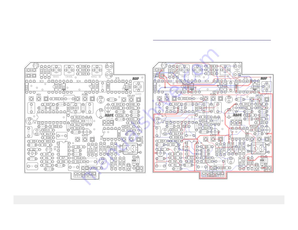
Aquaboy Deluxe (ABDX)

2015 edition

FX TYPE: Analog Delay

Based on the Boss® DM-2™

Download the previous (2013) version of the Aquaboy documentation here: 

http://www.madbeanpedals.com/projects/Aquaboy/docs/ABDX2013.zip

3.3” W x 3.2” H

Licensing: 

You are free to use Aquaboy Deluxe PCBs for DIY and small commercial building. You may not sell Aquaboy Deluxe PCBs on your own (selling to 

fellow DIY'ers through the forums is fine, of course) or re-package them as part of a “kit”.

Summary of Contents for ABDX

Page 1: ...ocumentation here http www madbeanpedals com projects Aquaboy docs ABDX2013 zip 3 3 W x 3 2 H Licensing You are free to use Aquaboy Deluxe PCBs for DIY and small commercial building You may not sell Aquaboy Deluxe PCBs on your own selling to fellow DIY ers through the forums is fine of course or re package them as part of a kit ...

Page 2: ... 1uF R11 150R R41 10k C11 100pF C43 100n R12 100k R42 22k C12 10uF Diodes R13 10k R43 100k C13 10uF D1 1N5817 R14 10k R44 100k C14 6n8 D2 8 2v Zener R15 10k R45 220k C15 100n D3 1n914 R16 10k R46 220k C16 330pF D4 LED R17 10k R47 4k7 C17 1uF Transistors R18 10k R48 1k C18 1uF Q1 Q4 MPSA18 R19 82k R49 1k C19 10uF I C R20 4k7 R50 1k C20 1uF IC1 LF353 R21 100k R51 1k C21 1uF IC2 NE570 R22 100k R52 10...

Page 3: ...4W 10k 1 100k 9 Metal Carbon Film 1 4W 1M 1 220k 2 Metal Carbon Film 1 4W 25k 2 470k 1 Metal Carbon Film 1 4W 50k 1 1M 1 Metal Carbon Film 1 4W VTL5C 3 1 see notes on modulation 100pF 5 Ceramic 25v min On Off On 1 Solder Lug 330pF 2 Ceramic 25v min 1MB 1 PCB Right Angle 16mm 470pF 1 Ceramic 25v min 100kB 1 PCB Right Angle 16mm 1n 1 Film 25v min 50kB 2 PCB Right Angle 16mm 2n2 1 Film 25v min 100kC ...

Page 4: ......

Page 5: ...1590BB Drill Guide 5 8 W x 6 83 H Download the Photoshop template here http www madbeanpedals com projects Aquaboy docs ABDX2015_DRILL zip ...

Page 6: ...True Bypass Wiring Jumper the two S1 pads Omit R58 R59 and jumper C40 instead of using the 1uF cap listed The bypass LED and D4 LFO rate indicator can be mounted directly to the PCB ...

Page 7: ...een added but is not yet tested on this project I have used this bypass on similar projects so it should work fine Note that Tails wiring is not true bypass The bypass LED and D4 LFO rate indicator can be mounted directly to the PCB ...

Page 8: ...ially available analog delays out there Indeed there are very few true analog delays with 500ms of delay and modulation that are under 200 Controls DELAY The total amount of signal delay from slapback to approximately 500ms FDBK The number and intensity of delay repeats from one to infinity self oscillation MIX The level of delay signal relative to the dry path of the guitar signal RATE The speed ...

Page 9: ...gnal continuously The lower the clock frequency the more delay you get but the further it creeps into the audio range Analog delays attempt to optimize the balance between signal degradation and clock bleed by a series of additional signal processing chains These are compression filtering and expansion The compressor portion beefs up the incoming signal to minimize its degradation while traversing...

Page 10: ...erior v3205 that will give you a full 500ms of delay from the ABDX Please keep in mind that these evaluations are in degrees not absolutes IOW it is entirely possible to build the ABDX with the v3205 to get the max delay and still get a very acceptable amount of fidelity the design has mods to help with this It s just never going to sound as good as the MN3005 running at 15v period The great thing...

Page 11: ... this The MN3205 v3205 and BL3208B require power on pin 5 and ground on pin 1 Setting these jumpers also changes whether the output resistors on the BBD pins 3 and 4 are pull up or pull down Again these will be different between the two groups of devices NOTE If you build the ABDX for one type of device and then later put in a different type you may have to switch the jumpers and or the voltage su...

Page 12: ...2 for the MN3008 If you are running the ABDX at 15v regulated then you should plan ahead how you will accomplish this You can use a Road Rage PCB to use a 9v supply to generate 15v regulated using the LT1054 chip or use an 18v adaptor then run it through a 15v regulator 220 type Consult the Road Rage documentation for more info on using a charge pump To regulate an 18v supply this method is sugges...

Page 13: ...ersion of the Mod board for the original Aquaboy project It uses an LFO to generate either triangle or square wave modulation which drives an LED LDR combo The LDR combines with the Depth pot to create a variable resistance to ground from lug 1 of the Delay control As the LED brightness fluctuates the resistance on the photocell goes up and down which creates an oscillating change on the overall d...

Page 14: ...kHz while probing either pin2 or pin4 of IC5 If you don t have this feature set the Clock trim half way up Remove IC4 temporarily Audio probe pin3 of IC3 while either strumming the guitar or send some audio through the input of the circuit Adjust the BIAS1 trimmer until you get delay passing The range over which the trimmer will result in delay is usually about 1 4 to 1 6 of its entire rotation Co...

Page 15: ... use 16mm short pin PCB mounted pots mounted underneath the PCB However I recommend against this unless you plan on building quite a few of these You may find that you need to remove a component or do some work underneath the PCB after you build it to troubleshoot Having wired pots instead of PCB mounted ones will make this MUCH easier The trimpots are spaced for Bourns 3362P which are about 25 on...

Reviews: