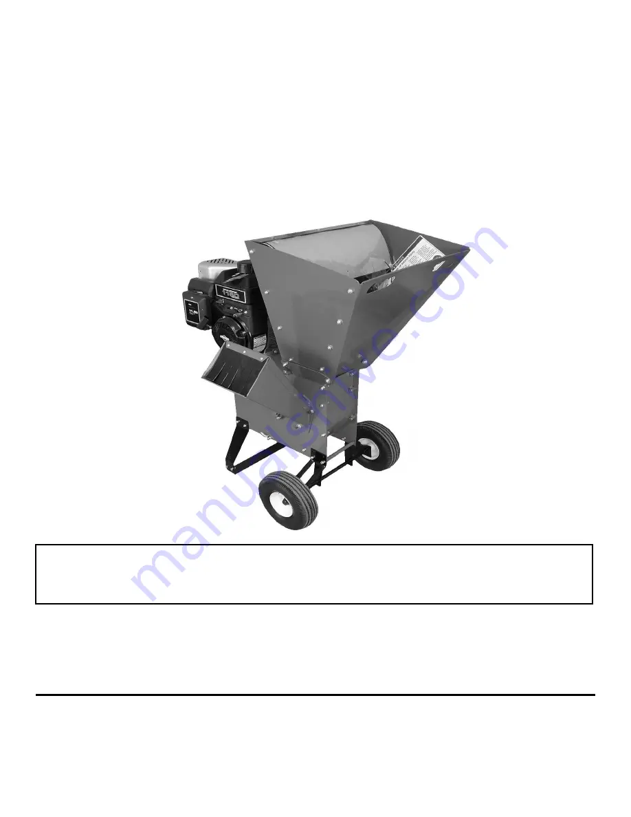
background image


OWNER’S MANUAL 

SC300M 

SHREDDER-CHIPPER 

ASSEMBLY AND OPERATING INSTRUCTIONS 


This manual contains information concerning proper and improper operating procedures, warnings, 

maintenance, trouble shooting, assembly, tips.  Everyone who operates this machine should read 

these instructions and be thoroughly familiar with them. 


THIS MACHINE IS CAPABLE OF INFLICTING 

SERIOUS INJURY IF OPERATED IMPROPERLY 

- READ WARNINGS AND CAUTION LABELS - 


MACKISSIC, INC.       P.O. BOX 111, PARKER FORD, PA       19457-0111 

PHONE:  1-800-348-1117                                   e-mail:  [email protected]                                    Fax:  (610) 495-5951 


3/2018 

Summary of Contents for SC300M

Page 1: ...tenance trouble shooting assembly tips Everyone who operates this machine should read these instructions and be thoroughly familiar with them THIS MACHINE IS CAPABLE OF INFLICTING SERIOUS INJURY IF OP...

Page 2: ...e this machine Be completely familiar with the controls and the proper use of this machine before operating it Failure to do so may cause serious injury to yourself or others Do not allow anyone to op...

Page 3: ...Rules Read this Safety Operating Instructions Manual before you use the shredder chipper Become familiar with the operation and service recommendations to ensure the best performance from your machine...

Page 4: ...your gloves fit properly and do not have loose cuffs or drawstrings Wear shoes with non slip treads when using your shredder chipper If you have safety shoes we recommend wearing them Do not use the m...

Page 5: ...edder chipper Hopper s to avoid accidental bounce back of any material Do not allow an accumulation of processed material to build up in the discharge area as this will prevent proper discharge and ca...

Page 6: ...with Spark Arresters Failure of the owner or operator to maintain this equipment in compliance with state regulations is a misdemeanor under California law and may be in violation of other state and o...

Page 7: ...The SHREDDER CHIPPER It may be helpful to familiarize yourself with the controls and features of your shredder chipper as shown in Figure 1 before beginning these procedures SHREDDER CHIPPER Controls...

Page 8: ...3 Use the Hand Slots in the Shredder Hopper to tilt and roll the machine from the Pallet 4 Remove the two Baffle Rods and Cotter Pins that go through the top of the Baffle Plate and the one behind it...

Page 9: ...ine is accidentally spilled move the machine away from the area of the spill Avoid creating any source of ignition until gasoline vapors have disappeared CAUTION Experience indicates that alcohol blen...

Page 10: ...y from the rotor and hammers Remember a technique and understanding is required to successfully shred or grind the great variety of materials which may be available to you for compost Branches are fed...

Page 11: ...lean out the Shredder Chipper Hopper s as instructed on page 14 ALWAYS operate the shredder chipper from the Operator Zones Figure 5 When viewed from the Chipper Hopper side the Rotor turns in a clock...

Page 12: ...gned to handle The revolving Chipper Knife mounted on a Rotor turns branches fed into the Hopper into chips The Chipper can chip twigs and branches ranging in size from 1 to 2 1 2 in diameter Cut your...

Page 13: ...is 3 4 Feed any larger material through the Chipper Hopper Material larger than 3 4 can cause serious damage to any of the internal parts of the Shredding Chamber Inspect the shredder chipper after ev...

Page 14: ...erial into the Hopper clogging could result in Belt or Clutch failure To Clean Out a Clogged Shredder 1 Remove the Baffle Plate by removing the Nut on the Baffle Rod and then removing the Baffle Plate...

Page 15: ...nect the Spark Plug Wire keeping it away from the Spark Plug Regular Maintenance Checklist PROCEDURE BEFORE EACH USE EVERY 8 10 HOURS EVERY 40 HOURS EVERY 100 HOURS Check Engine Oil Level Check Genera...

Page 16: ...ring If they are loose reset them with Loctite 243 obtainable at most hardware stores Tensioning Replacing and Aligning the Drive Belt Use only a factory Belt on your machine The Belt has been thoroug...

Page 17: ...hen the Belt is at the proper tension tighten the Engine Hardware 5 Screw the Tag Nut up to the Adjust Nut 6 Replace the Baffle Plate and Belt Guard CHECKING AND SETTING BELT ALIGNMENT Tools and Suppl...

Page 18: ...g and Setting Belt Tension section 4 Reinstall the Belt Guard NOTE Check and re tighten if necessary the Drive Belt after an initial break in period of one hour Knife Sharpening You should never attem...

Page 19: ...o support the Rotor by inserting a block of wood under the knife while loosening the Locknuts and Screws Figure 20 6 Repeat Step 5 for the remaining two Allen Screws 7 Remove the dull or damaged Knife...

Page 20: ...re 23 6 Drive out the Roll Pin with a punch and Hammer 7 Align the Rod with the Access Hole 8 Carefully remove the Rod through the Access Hole and at the same time remove the Hammers and spacers from...

Page 21: ...e driven unit NEVER operate the SHREDDER CHIPPER Engine at less than full RPM Tools and Supplies Needed Two 1 2 Wrenches 9 16 Wrench Anti seize compound 1 Remove the Belt as described in the Replacing...

Page 22: ...g the procedure in the Engine Owner s Manual The gas may be old change it if necessary Use a fuel stabilizer if you keep gas longer than one month Check the Throttle and Choke settings adjustment and...

Page 23: ...broken Shredding and chipping action seems too slow or Rotor stalling The Engine speed is too slow causing the Belt to slip Run the Engine at full throttle Check for loose or damaged Drive Belt tighte...

Page 24: ...048 Locknut 5 16 18 04 030 0055 Bearing 05 800 0207 Drive Side Weldment 06 090 0088 Bolt HHCS 5 16 18 x 1 07 800 0218 Rotor Assembly Ref Part Description 08 090 0391 Bolt HHCS 5 16 18 x 8 Blk 09 020 0...

Page 25: ...Schematic BASIC MACHINE ASSEMBLY 25...

Page 26: ...rt Description 2 090 0066 Bolt HHCS 5 16 18 x 3 4 3 090 0460 Nut Nylon Lock 5 16 18 4 800 0145 Leg 5 800 0100 2 Spacer Pipe 7 090 0391 Bolt HHCS 5 16 18 x 8 8 030 0641 Wheel 4 10 3 50 x 4 9 090 0457 C...

Page 27: ...er Lock 3 8 6 704 0106 Washer 7 030 0615 Belt 8 030 0608 Pulley 9 500 0031 Key 1 4 x 1 4 x 1 10 090 0090 Bolt HHCS 5 16 18 x 1 1 2 11 930 0360 Tensioner Belt 12 030 0651 Engine 13 080 0053 Screw Set 5...

Page 28: ...460 Nut Nylon Lock 5 16 18 07 800 0015 Screen 08 800 0012 Plate Baffle 09 800 0013 Rod Screen and Baffle 10 913 0385 Shield Blowback 11 913 0384 Hopper Chipper 12 090 0704 Screw PHMS 10 24 x 3 4 13 09...

Page 29: ...Schematic HOPPERS AND SCREEN 29 5...

Page 30: ...5 16 18 02 800 0211 Hopper Side 03 800 0209 Hopper Top 04 090 0470 Nut Nylon Lock 1 4 20 05 090 0502 Washer Fender 06 800 0198 Shield Blowback 07 090 0731 Screw Truss Head 5 16 18 x 1 2 08 800 0210 H...

Page 31: ...Schematic SHREDDER HOPPER 31...

Page 32: ...800 0217 Rotor Weldment 02 900 0100 5 Rod Hammer 03 090 0626 Pin Roll 04 500 0010 Spacer 5 16 05 500 0012 Spacer 5 8 06 500 0011 Spacer 7 8 07 500 0008 Hammer 08 090 0460 Nut Nylon Lock 5 16 18 09 030...

Page 33: ...Schematic ROTOR ASSEMBLY 33...

Page 34: ...Notes 34...

Page 35: ...Notes 35...

Page 36: ...will be idle for more than 30 days we recommend using a gas stabilizer This will prevent sediment from gumming up the Carburetor If there is dirt or moisture in the gas or tank remove it by draining...

Page 37: ...bled or installed as specified in the owner s manual The warranty does not cover any product that has been altered or modified In addition the warranty does not extend to repairs made necessary by nor...

Reviews: