


1
Original
Version 1-2011
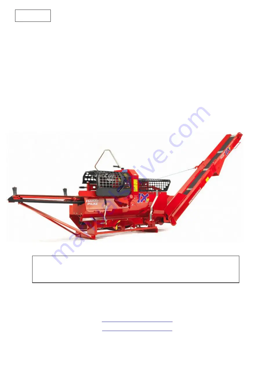
HakkiPilke 37
Expert/Easy
LOG SPLITTER
- Instructions for assembly, operation and maintenance
- EU Declaration of Conformity
- Safety instructions
- Warranty terms
MAASELÄN KONE OY
Valimotie 1, FI-85800 Haapajärvi, Finland
Tel. +358 (0)8 7727300, Fax +358 (0)8 7727320
ENGLISH
The operator must read and understand these
instructions before operating the log splitter!


