Ludwig CSB70, Manual
The Ludwig CSB70 is a high-quality manual drum set designed for maximum performance and flexibility. With its user-friendly features and excellent sound quality, this instrument is perfect for both beginners and professional drummers. You can easily download the free user manual from manualshive.com to make the most out of this exceptional drum set.
Share
Download


Reviews:
No comments
Related manuals for CSB70
ECO 4
Brand: 4pets Pages: 2
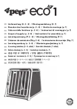
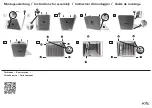
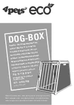
ECO 1
Brand: 4pets Pages: 5
ECO Series
Brand: 4pets Pages: 56

SCENAR 1-NT
Brand: RITM OKB ZAO Pages: 47

SKY5513
Brand: BCP Pages: 8

Vergiss nix-4
Brand: Scala Pages: 2

NoBark 10R
Brand: SportDOG Pages: 20

HEADS FIRST
Brand: Matrix Seating Pages: 4

PHLIRG39
Brand: PYLE HEALTH Pages: 8

AD 2225
Brand: Adler Europe Pages: 64

LS-78D1SB
Brand: ARISTORM Pages: 51

Professional Nail Dust Collector
Brand: MelodySusie Pages: 8

RESET & BOOST SKIN DUO
Brand: Rowen Pages: 4

nobu Mika
Brand: Bodispa Pages: 2

Tru-Shape
Brand: Permobil Pages: 28

FeatherStone Heights Victorian
Brand: Prevue Hendryx Pages: 2

iLook move 17612 019051
Brand: KEUCO Pages: 12

Mirror Iseo
Brand: ESS Pages: 20


