background image

Copyright 

©

 2007 LOREX Technology Inc. 

www.lorexcctv.com


 5”B&W Rear View 

Safety System

Instruction Manual

English Version 1.0

MODEL:

RV453

Summary of Contents for RV453

Page 1: ...Copyright 2007 LOREX Technology Inc www lorexcctv com 5 B W Rear View Safety System Instruction Manual English Version 1 0 MODEL RV453 ...

Page 2: ...OISTURE CAUTION TO PREVENT ELECTRIC SHOCK MATCH WIDE BLADE OF PLUG TO WIDE SLOT FULLY INSERT Thank you for purchasing the Lorex 5 Black White Rear View Safety System This system helps to prevent backing up and parking accidents by allowing you to view or check on the traffic behind your vehicle or when rounding corners blind spot prevention This system is suitable for waste trucks RV campers vans ...

Page 3: ...cted z Consult the dealer or an experienced radio or television technician for assistance LOREX TECHNOLOGY INC http www lorexcctv com NOTE This equipment has been certified and found to comply with the limits regulated by FCC EMC and LVD Therefore it is designated to provide reasonable protection against interference and will not cause interference with other appliance usage However it is imperati...

Page 4: ...dix 3 14 RV453 FEATURES Automatic activation of camera when gear is shifted into reverse Built in 2 Camera input Built in microphone on camera One way audio Built in Brightness Contrast and Volume Control Selector switch for Normal and Reverse image viewing Waterproof B W CCD image sensor camera in a compact die cast housing Input voltage 12 32 Volt DC Monitor equipped with day night selector swit...

Page 5: ...nts CHECK YOUR PACKAGE TO CONFIRM THAT YOU HAVE RECEIVED THE COMPLETE SYSTEM INCLUDING ALL COMPONENTS SHOWN ABOVE Mounting Hardware and Brackets for Monitor and Camera 65 2 Piece Camera Ex tension Cable Sunshade for Monitor Power cable and Harness 1 3 CCD Weatherproof Camera 5 B W CRT Monitor ...

Page 6: ...e the volume and counterclockwise to decrease it 5 CAMERA SWITCHER C1 C2 Press the Camera Switcher button to switch the picture view from Camera 1 to Camera 2 second camera is sold separately Press the button in to switch to Camera 1 Press the button again to switch to Camera 2 NOTE When the vehicle changes into reverse gear the system will automatically display the picture from Camera 1 regardles...

Page 7: ...V or monitor using an Audio RCA cable not included or to the Audio input of a VCR DVR for recording 4 EXTERNAL SPEAKER PORT Connects the system to external Speakers not included 5 MIRROR NORMAL SWITCH Changes the view on Camera 1 and Camera 2 to Mirrored or Normal view NOTE This switch has been set to Mirror Reversed Image during production When viewing behind the vehicle when reversing confirm th...

Page 8: ...and tighten the screws 3 Install the camera to the bracket using the supplied washers spring washers and screws 4 Adjust the camera to the desired position make sure the picture is clear and pointed in the correct direction Tighten the screws 5 Drill a cable entry hole through the frame door or window frame just below the mounting bracket 6 Pull the cable fully through the hole Once the cable has ...

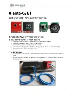
Page 9: ...9 Camera Overview Camera Overview Monitor Overview ...

Page 10: ...t position and tighten the screws 3 If necessary attach the sun shield on top of the monitor Connecting the Monitor and Cables 1 Connect the cameras to the camera input sockets marked C1 and C2 on the back of the monitor NOTE Connect the backup reverse gear camera into the C1 camera 1 port 2 Plug the power harness into the socket marked POWER at the back of the monitor Connecting the Monitor Power...

Page 11: ...e R reverse gear 4 Connect the WHITE wire to the Dimmer line Operating Instructions When you turn the ignition key to the ON position power is supplied to the monitor The monitor will automatically be in standby mode even if the Power button is not pushed in When you push the power button you can manually view the picture from the camera s When the power button is not pushed in and you shift the g...

Page 12: ...2V input Black Ground White Dimmer Inputs 4 pin multi connector 1 Video input 1 0 Vp p 75ohm 2 Audio 3 12V 0 2A DC output 4 Ground Audio Output S P 8 ohm 0 5 watt max Audio Output phone Jack 10K 150 mV ms Video Output phone jack 75 ohm 1 Vp p Power Requirements 12V 32V DC negative ground Power Consumption 10 5 W Maximum Operating Temperature 5 F 140 F 15 C 60 C Storage Temperature 13 F 185 F 25 C ...

Page 13: ...d without incurring any obligation E OE Pick up Device 1 3 B W CCD Number of Pixels 512 x 492 EIA Fixed Focus Lens 2 5mm Viewing Angle 110 Diagonal Horizontal Resolution 380 TV Lines Video Output 1V p p 75 ohms Minimum Illumination 0 3 Lux Shock Vibration Rating 6 8g 0 2000 Hz Input Voltage Range 9 5 14V DC from the monitor Operating Temperature 14 F 122 F 30 C 50 C Dimensions 2 76 W x 1 97 H x 1 ...

Page 14: ...systems Adaptor Cable 3 CA453 Camera to CA452 Camera Extension Cable Connects the Lorex CA453 Camera to the Sentinel CA452 Camera Extension Cable Adaptor Cable 2 CA453 Camera Extension Cable to MO452 Monitor Connects the Lorex CA453 Camera Extension Cable to the Sentinel MO452 Monitor Adaptor Cable 1 CA452 Camera Extension Cable to MO453 Monitor Connects the Sentinel CA452 Camera Extension Cable t...

Page 15: ...It s all on the web Product Information User Manuals Quick Start Guides Specification Sheets Software Upgrades Firmware Upgrades Lorex Technology Inc VISIT wwwlorexcctv com www lorexcctv com ...

Page 16: ......

Reviews: