background image

Copyright 

©

 2010 Lorex Technology Inc. 

www.lorextechnology.com

Lorex-Edge

+

 LH320 Series

Lorex Edge mini LH304 Series

Lorex EDGE LH310 Series

LH300 SERIES

INSTRUCTION MANUAL

English Version 2.0

NETWORK READY H.264 HIGH PERFORMANCE 

DIGITAL VIDEO SURVEILLANCE RECORDER

MODEL:

LOREX EDGE 

Summary of Contents for LH300 SERIES

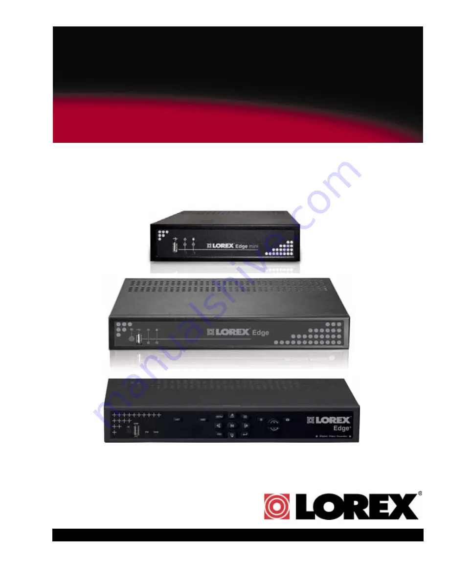
Page 1: ...w lorextechnology com Lorex Edge LH320 Series Lorex Edge mini LH304 Series Lorex EDGE LH310 Series LH300 SERIES INSTRUCTION MANUAL English Version 2 0 NETWORK READY H 264 HIGH PERFORMANCE DIGITAL VIDEO SURVEILLANCE RECORDER MODEL LOREX EDGE ...

Page 2: ...l triangle is intended to alert the user to the presence of uninsulated dangerous voltage within the products enclosure that may be of sufficient magnitude to constitute a risk of electric shock The exclamation point within an equilateral triangle is intended to alert the user to the presence of important operating and maintenance servicing instructions in the literature accompanying the appliance...

Page 3: ...omer Care for warranty and accessory sales customerservice lorexcorp com Customer Feedback info lorexcorp com Product Support is available 24 7 including product information user manuals quick start up guides and FAQ s at www lorextechnology com support Online To order accessories visit www lorextechnology com DO NOT RETURN THIS PRODUCT TO THE STORE NEED HELP CONTACT US FIRST 3 EASY WAYS TO CONTAC...

Page 4: ...ez www lorextechnology com Veuillez veiller à enregistrer votre produit à www lorexcctv com registration pour recevoir des mises à jour et l information de produit Cerciórese de por favor colocar su producto en www lorexcctv com registration para recibir actualizacio nes y la información del producto NECESITA AYUDA COMUNÍQUESE PRIMERO CON NOSOTROS VOUS AVEZ BESOIN D AIDE CONTACTEZ NOUS D ABORD Pou...

Page 5: ...s product Consumer Guides and Video Tutorials are available on our web site at www lorextechnology com support If you require further installation assistance please visit www lorextechnology com installation or contact a professional installer Please refer to the Need Help insert for technical support and customer care information Please note that once the components of this product have been unse...

Page 6: ...rer à l insert Need Help pour ob tenir de l information sur le service à la cli entèle et le support technique Veuillez constater qu une fois que les com posantes de ce produit ont été retirées de l emballage vous ne pourrez plus retourner ce produit directement au magasin Favor de leer la guía de instalación rápida y la guía del usuario antes de instalar este producto Puede conseguir las guías de...

Page 7: ...it replaced by your service technician 7 Power Cord Protection Power supply cords should be routed so that they are not likely to be walked on or pinched by items placed upon or against them paying particular attention to cords at plugs convenience receptacles and the point where they exit from the video product 8 Ventilation Slots and openings in the case are provided for ventilation to ensure re...

Page 8: ...r can prevent fire electric shock or other hazards 16 Safety Check Upon completion of any service or repairs to this video product ask the service technician to perform safety checks recommended by the manufacturer to determine that the video product is in safe operating condition 17 Wall or Ceiling Mounting The cameras provided with this system should be mounted to a wall or ceiling only as instr...

Page 9: ...of this product the specifications are subject to change without notice from time to time FCC CLASS B NOTICE Note This equipment has been tested and found to comply with the limits for a Class B digital device pursuant to Part 15 of the FCC Rules These limits are designed to provide reasonable protection against harmful interference in a residential installation This equipment generates uses and c...

Page 10: ... phones7 Exclusive LOREX Easy Connect Internet Set up Wizard8 PC Microsoft Windows 7 Vista XP compatible using Internet Explorer browser Apple Mac compatible using the Safari browser for multi channel live viewing Free LOREX DDNS Dynamic Domain Name Service for advanced remote connectivity at all times Email notification of events 1 Recording capacity may vary based on recording resolution quality...

Page 11: ...R Extender 8 6 Connect the Power 8 System Passwords 9 Mouse Control 9 Remote Control 10 Starting the System 11 Onscreen Display 11 4 channel 11 8 16 channel 13 Using the Split Screen Selector 15 Live Viewing 15 Playback 15 Flexible Camera Assignment 16 Setting the Date and Time 17 Recording 18 Event Recording 18 Recording Audio 18 Playback 19 Playback Markers 20 Additional Search Markers 20 Event ...

Page 12: ... 34 4 channel 34 8 16 channel 36 Motion 37 4 8 16 channel 37 Backup 38 Formatting the USB Drive 38 Confirming Backup 39 Backup File Information 39 Setting Quicktime as a default media player 39 LAN 40 Easy Connect 40 LAN Password 41 Upgrading Firmware 41 Changing Ports On Your System 42 REMOTE ACCESS DVR Netviewer 46 System Requirements 46 Netviewer Basic Layout 47 Network User Profiles 47 DVR Net...

Page 13: ...h Drive 62 Download the firmware from the Lorex website 63 Upgrade the DVR firmware 63 Enabling Easy Connect on your DVR 63 Registering for an Easy Connect account 64 Connecting to your DVR using Easy Connect 66 How port forwarding works 68 Lorex Auto Port Forwarding Wizard 69 Installation 69 Obtaining Your Router Model Number and Version 70 Example 70 Configuration 71 Initial Startup Select langu...

Page 14: ... to your DVR using Mobile View 84 Mobile Connectivity on the Blackberry 85 Appendix A System Specifications 89 EDGE SERIES DVR 89 Appendix A System Specifications cont d 90 EDGE SERIES DVR 90 Product Information 90 Edge and Edge Mini Specifications 91 Appendix B Connecting Motion Alarm Devices 94 PTZ Control Interface 97 Appendix C Connecting Audio 99 Appendix D Full Connectivity Diagram 101 Appen...

Page 15: ...ting Kit Mounting Kit contents may differ from image Ethernet Cable Instruction manual quickstart guide documentation CD Remote Control DVI VGAAdapter USB Mouse Flex IR Extender Power Adapter Mounting Kit Mounting Kit contents may differ from image Ethernet Cable Instruction manual quickstart guide documentation CD EDGE mini DVR LH304 DVR MODEL HARD DRIVE SIZE NUMBER OF CHANNELS AND CAMERA CONFIGU...

Page 16: ...nel 1 GND Ground port 2 DC 12V Port for 12V DC 2 5A power adapter included 3 VGA Port to connect a VGA monitor not included 4 Audio In Input ports for audio enabled cameras Audio Out Output for two audio channels 5 Video In BNC input ports for 4 BNC cameras 6 USB Port Port for a USB mouse 7 LAN Networking port for a 10 100 Base T RJ 45 network cable included 8 Flex IR port Port for the Flex IR Ext...

Page 17: ...el models 1 Exhaust slots Slots to let heat escape from the internal hard drive Do not block Allow for proper ventilation 2 DC 12V Port for 12V DC 2 5 A power adapter included 3 Alarm I O Input output port for alarm relay D sub 9 connector required not included 4 Audio In Input ports for audio enabled cameras 5 Video In BNC input ports for 4 BNC cameras 6 USB Port Port for a USB mouse 7 LAN Networ...

Page 18: ... USB Port Port for a USB mouse 9 DC 12V Port for 12V DC 3 A power adapter included 10 Ground Port 16 channel 1 Video In BNC input ports for 16 BNC cameras 2 Audio In Input ports for audio enabled cameras 3 Alarm I O Input output port for alarm relay D sub 9 connector required not included 4 Audio Out Output for two audio channels 5 DVI Port to connect a DVI monitor not included 6 LAN Networking po...

Page 19: ...channel view changes display view to Quad split screen 4 channel model only S CH Move cursor in menus up Channel Up X FWD Move cursor in menus right during playback increase forward playback speed 5X 15X 60X W REW Move cursor in menus left during playback increase reverse playback speed 5X 15X 60X Start pause forward playback T CH Move cursor in menus down Channel down ESC Go back exit menus Confi...

Page 20: ...for a 10 100 Base T RJ 45 network cable included 8 IR Port for the Flex IR Extender 9 Ground Port 8 channel 1 Video In BNC input ports for BNC cameras 2 Audio In Input ports for audio enabled cameras not included Audio Out Output for two audio channels 3 Alarm Block Input output port for alarm relay devices i e PTZ cameras and sensors not included 4 DVI Port to connect a DVI monitor not included 5...

Page 21: ...nnels 3 Alarm Block Input output port for alarm relay devices i e PTZ cameras and sensors not included 4 DVI Port to connect a DVI monitor not included 5 LAN Networking port for a 10 100 Base T RJ 45 network cable included 6 IR Port for the Flex IR Extender 7 USB Port Port for a USB mouse 8 DC 12V Port for 12V DC 3A power adapter included 9 Ground Port 5 8 3 1 2 4 6 7 9 ...

Page 22: ...ernet cable to an empty LAN port on your router not included 5 Connect the Flex IR Extender a Connect the Flex IR extender to the port on the rear panel of the DVR Position the Flex IR extender near the front of your monitor or where it will receive a clear signal from the remote control Use a piece of double sided tape included to help secure the Flex IR Extender NOTE The Flex IR Extender is not ...

Page 23: ...lick to select a menu option while in Split Screenmode LiveVieworPlayback clickonachannel to view the selected channel in full screen Right Button Click to return to previous menu exit menus modes 3 Scroll Wheel Scroll up down to change values in selected menu options position markers in playback bar LEVEL ID PASSWORD USER 1 1111 ADMIN 2 2222 LEVEL ID PASSWORD USER 2 2222 ADMIN 3 3333 LEVEL ID PAS...

Page 24: ...nus up Channel Up X FWD Move cursor in menus right during playback increase forward playback speed 5X 15X 60X W REW Move cursor in menus left during playback increase reverse playback speed 5X 15X 60X Start pause forward playback T CH Move cursor in menus down Channel down ESC Go back exit menus Confirm menu selections 4 While in Event List menu press to delete a selected event no confirm or undo ...

Page 25: ...ve Mode NOTE Make sure all cameras and cables are properly connected prior to powering on the system Onscreen Display 4 channel 1 System Status Bar Displays mode password type recording mode language and status of devices HDD and USB 2 Display Full screen single channel and Quad split screen available in Live Viewing and Playback modes if cameras are disconnected channels display a blue screen wit...

Page 26: ...ick to increase reverse playback speed 5X 15X 60X From Live View click to open Playback Mode click to pause play video While in Playback mode click to increase forward playback speed 5X 15X 60X Click to open the Event List menu See Event List on page 21 Click to begin sequence view From the Event List menu click to delete a selected video file NOTE Be careful when clicking the Trash icon there is ...

Page 27: ...s in progress 4 Date Time Displays the date and time on the system 5 HDD Status Displays the recording space consumed on the hard disk and the size of the pre installed hard drive For example 250 GB This reading is an approximation 6 Toolbar Primary control input for the user interface certain buttons will not be available at all times Figure 4 2 Live viewing with onscreen display 16 channel model...

Page 28: ...Playback mode click to increase forward playback speed 5X 15X 60X Click to open the Event List menu See Event List on page 21 Click to begin sequence view Click to show hide the on screen display OSD Click to return to the previous menu and or quit menus modes Opens the PTZ menu PTZ camera required not included EDGE LH320 series only From the Event List menu click to delete a selected video file N...

Page 29: ...the Split Screen Selector Grid configurations appear in circles onscreen 2 Click a grid configuration for live viewing 8 channel Choose from quad CH1 4 CH5 9 or 9 split CH1 8 the bottom right square will remain blacked out 16 channel Choose from quad CH1 4 CH5 9 CH9 12 CH13 16 9 split CH1 9 CH10 2 or 16 split CH1 16 Playback To use the Split Screen Selector 1 During playback click at anytime to op...

Page 30: ...tems only NOTE The system continues to record the designated channel even if you re assign camera positions To re assign camera positions 1 Select the channel you want to have re assigned 2 Click and hold the mouse A channel menu appears 3 While holding left click move the mouse to the left or right to change the channel number 4 Release left click on the mouse to assign the new channel EXAMPLE Ch...

Page 31: ...p and configure the following options Date Mode Use the scroll wheel to select Y M D D M Y or M Y D Date Use the scroll wheel to manually enter the date Time Use the scroll wheel to manually enter the time 4 Click Exit Update The new date and time are saved the system returns to the Setup menu 5 Right click to exit until all menus are closed The date and time will appear on the bottom left corner ...

Page 32: ...cludes three modes of event recording Motion The system records when motion is detected by the affected camera Alarm The system records when an alarm or sensor is triggered Video Loss The system records when a camera is disconnected or suffers video loss The system employs a pre record function to capture video seconds before the video loss occurred Recording Audio The system can record two audio ...

Page 33: ...15X 60X Click to increase forward playback speed 5X 15X 60X Click to open the Split Screen Selector 8 16 channel only Click to view playback in Quad mode 4 channel only Click to open the Event List menu See Playback Mode on page 24 4 Click any channel to view the selected channel in full screen or click 5 Click anywhere in the playback bar to set a playback marker Playback Markers can be used for ...

Page 34: ...l Search Markers The Playback bar can also be populated with other multi colored markers These markers are part of the Smart Search functionality of the system For more details on Smart Search see Event List on page 21 To use the search markers 1 Using the mouse scroll up down to position one of the colored markers in the Playback Target 2 Click Figure 6 1 Playback display view ...

Page 35: ...ent Details View details for the event including date time and event source 4 Events List of recorded events on the system 5 Active Toolbar Buttons While in Event List use Play Pause Trash delete and C Escape NOTE The Escape button is only on Edge and Edge mini models Screenshot button appears on 8 16 channel models Channel Filter Use the Channel Filter to sort the data from individual channels or...

Page 36: ...t Details The event details event number camera on off filter type date time and event source immediately match the list of events When you use the Camera filter and Event filter the Event Details bar can help you view the pertinent information for the data Figure 7 1 Smart Search Icons Event Number Camera ON OFF Filter Type Date Time Event Source Figure 7 2 Event Details icons ...

Page 37: ...e USB flash drive with saved backup data is connected Motion Motion events from the connected cameras Video Loss Cameras are disconnected or suffer video loss The system employs a pre record function to capture video seconds before the loss of video occurred Alarm Alarm or sensor events on the system HDD ON OFF Disconnection power loss or disk failures on the hard drive Power ON OFF System ON OFF ...

Page 38: ...r ALL channels or click the Channel icons to view events from individual channels 4 Click any of the Smart Search icons to filter your search 5 Scroll up down to view the events on the list 6 Click an event from the Event List and then click Playback begins for the selected file NOTE You cannot begin playback after clicking or You can click while a file is playing Playback will pause Select a new ...

Page 39: ...ront panel of the system Format the USB flash drive if you have not already done so For more details see Formatting the USB Drive on page 38 2 If you want to capture a point in live viewing or playback select the display view for the screenshot single quad or split screen 3 Click The screenshot will appear in the centre of the main display followed by the file name Screenshots are saved to the Pic...

Page 40: ...lder to view files NOTE If AutoPlay does not start search your computer for a Removable Disk 2 Double click the Picture folder 3 Perform one of the following View Double click the screenshot to view it in an imaging program such as Windows Picture Viewer or Adobe Photoshop Archive Copy the images to a folder on your computer Print Select the image and print it directly from Windows Explorer or pri...

Page 41: ...By default passwords are disabled when you first startup the system With passwords enabled you need to enter your user ID and password whenever you access the system Main Menu Event List or Playback mode To enable disable passwords 1 Click to open the Main Menu If necessary login to the system 2 Click The Setup menu opens 3 Click Password Enable and scroll up down to select O to enable passwords o...

Page 42: ...OTE In older firmware models click 2 Click The Setup menu opens 3 Click DVR Password The Password Wheel opens 4 Log in as the administrator 5 Click either User Password or Admin Password 6 Use the Password Wheel to input a 4 digit password Input it again to confirm 7 To exit right click until you return to the main screen Figure 8 1 Password change Figure 8 2 Password confirmation ...

Page 43: ...igure Date Time Language video system passwords and view system information 3 Record Configure recording parameters for Alarm Motion recording and working non recording adjust video quality resolution set record mode schedule and format the hard drive 4 Alarm Configure alarm motion and video loss settings 5 Backup Set backup parameters format connected USB flash drive 6 LAN View configure networki...

Page 44: ...u bar NOTE SequenceTimereferstothetimethe camera channel changes to the next camera channel in single channel view Setup Set date time system language passwords and view system information To configure Setup settings 1 From the Main Menu click The Setup menu opens 2 Configure the following Load Default Click to load default factory settings Language Select English Traditional Chinese Spanish Russi...

Page 45: ...on the hard drive To configure record settings 1 From the Main Menu click The Record menu opens 2 Configure the following Alarm Motion Rate Click under each camera and select X 2 3 5 7 5 10 or 15 fps Working Hour Rate Click under each camera and select 0 2 3 5 7 5 10 or 15 fps Non working Hour Rate Click under each camera and select 0 2 3 5 7 5 10 or 15 fps Quality Click under each camera and sele...

Page 46: ...ty statistics Record Mode Click to select one of the following z Single Way The system stops recording when the internal hard drive is full z Overwrite The system continues recording when the internal hard drive is full by overwriting the oldest recorded data z No Record The system does not record VideoFrameRate Settheframeratesfor alarm motion working hour and non working hour z Alarm Motion Rate...

Page 47: ...ecording is known as Working Hour yellow and non recording is known as Non working Hour green NOTE As you make changes to the recording parameters the storage calculator at the bottom of the menu displays the time remaining on the hard drive To set a recording schedule 1 From the Record menu click Schedule The Recording Schedule grid opens 2 Click an hour square 0 23 in each weekly row Sun Sat act...

Page 48: ...k The Alarm menu opens 2 Click and edit the following Video Loss Alarm Click under each camera and select either O to enable the VLoss alarm or X to disable it If enabled the system will sound an alarm whenever one of the connected channels incurs a loss of video Motion Enable Click under each camera and select O to enable motion detection or select X to disable it If enabled the camera can record...

Page 49: ...nd assign it to the desired camera number Alarm Out Setup Menu To configure the Alarm Out Setup menu 1 Click Alarm Out Setup 2 Click to assign an Event notification Motion VLoss Alarm HDD ON OFF to an Alarm Out notification Buzzer Alarm Full Screen Label Alarm Out 1 Buzzer Select O to enable the system to beep when an alarm is triggered or motion is detected select X to disable it Alarm Full Scree...

Page 50: ...stem to beep when an alarm is triggered or motion is detected select X to disable it Key Buzzer Select O to enable the systembeepwhenyouclickthemouse press the buttons on the remote front panel Select X to disable the beep AlarmInput Output Click to open the Alarm Input Output menu Alarm In Type Select OFF NO normallyopen NC normallyclosed to select alarm type Alarm In Setup Click to open the Alar...

Page 51: ...a 2 Choose a camera for motion detection and select O 3 Click Motion Select the camera you want to configure motion detection The motion grid appears for the selected camera 4 Click within the grid to enable disable individual motion cells Enabled cells are light green disabled cells are clear 5 Click the Sensitivity bar at the bottom of the screen Scroll up down to increase decrease the sensitivi...

Page 52: ...t panel NOTE Do not connect a USB flash drive to the USB port on the rear panel Only the port on the front panel has been designed for backup data transfer 2 From the Main Menu click The Backup menu opens 3 Click Start Time and select the date month year and time to begin the backup Event Markers will appear in the Time Bar as you scroll through the date and time 4 Click Stop Time and select the d...

Page 53: ...u saved the MOV file by default C By default converted files use the following naming convention bv3 mov 2 Double click the file to open it in QuickTime Player Setting Quicktime as a default media player It is recommended to set Quicktime as your default media player This allows you to double click on a backed up video file and have the file play automatically To set Quicktime as your default play...

Page 54: ...that port forwarding will not change in the event of power failure or resetting of your network NOTE For added security we strongly recommend changing HTTP port 80 on the system to any desired port not blocked by your Internet service provider ISP For details on changing ports on your system see Changing Ports On Your System on page 42 Easy Connect Use the Easy Connect menu to enable Easy Connect ...

Page 55: ...hese free upgrades from www lorextechnology com Prior to upgrading your system s firmware you must first format the USB flash drive so it will function properly with the system To upgrade firmware 1 Connect a USB flash drive to the USB port on the front panel of the DVR and format see Formatting the USB Drive on page 38 Once formatting is complete remove the USB flash drive and connect it to a USB...

Page 56: ... the scroll wheel or press on the remote control to change the port number to 85 4 Right click to exit and save your settings or press the ESC button on the remote control 5 Disconnect the power cable from the rear panel of the system Let the system power down for 15 20 seconds and then reconnect the power cable 6 To confirm that the new port number is saved on your system the button twice on the ...

Page 57: ... Local Viewing To log in using the new port number 1 Open Internet Explorer 2 In the address bar enter http then the IP address of your system immediately followed by 85 no spaces For example http 192 168 1 89 85 3 Enter your LAN ID and password to log in to your system using DVR Netviewer Figure 15 4 Enter 85 at the end of the IP address Figure 15 6 Login with your LAN ID and password ...

Page 58: ...ds and then reconnect the power cable 7 To confirm that the DDNS information is saved on your system press the button twice on the remote control to view the System Information 8 If you have not already done so use the Auto Port Forwarding Software included on CD to port forward port 85 on your router or Manually port forward your router Each router is different so port forwarding settings vary by...

Page 59: ...ote viewing requires Internet Explorer 6 or later To log in using DDNS 1 Using a remote PC open Internet Explorer 2 In the address bar enter your DDNS address immediately followed by 85 no spaces NOTE Obtain your DDNS address from your confirmation email 3 Enter your LAN ID and password to log in to your system If you are having problems connecting using DDNS check that you have port forwarded por...

Page 60: ...m Core Duo 1 66 Ghz or above Mac Operating System Windows XP Vista 7 Apple OSX 10 5 or above Memory 128 MB RAM Video 16 MB of video memory Network LAN 10 100 BaseT Network Network WAN 384 Kbps upstream High speed Internet service is recommended when using DVR Netviewer Browser Internet Explorer 6 or later Mozilla Firefox is also supported but you need to install the IE Tab plug in http addons mozi...

Page 61: ...o login to DVR Netviewer you need a network user ID and password Use the following default network user IDs and password to login to DVR Netviewer Figure 17 0 Four channel Netviewer Figure 17 1 Sixteen channel Netviewer LEVEL ID PASSWORD GUEST 7 1111 USER 8 2222 ADMIN 9 3333 4 8 16 Channel Remote LAN Viewing ...

Page 62: ...k to view live streaming video view single channels in full screen or view all channels in quad split screen PLAYBACK Click to view recorded video from the system Select channel and enter date and time playback controls appear when Playback mode selected BACKUP Click to save recorded video data to your PC SETUP Click to open the Setup menu Not available on Safari Mac 4 Views Click to view in Quad ...

Page 63: ...nnels in quad split screen PLAYBACK Click to view recorded video from the system Select channel and enter date and time playback controls appear when Playback mode selected BACKUP Click to save recorded video data to your PC SETUP Click to open the Setup menu Not available on Mac 4 Views Click to view in Quad 1 4 5 8 9 12 13 16 and 16 split 5 Channels Click to view channels in full screen NOTE PTZ...

Page 64: ...Channel buttons to select the channel you want to view 3 Click to open a pop up calendar to select the date and time 4 Click to control playback Using the Pop Up Calendar To use the pop up calendar 1 Click to change the month 2 Select a date 3 Click to set the time OR Drag the slider to adjust time in 30 minute increments 4 Click SET The pop up calendar closes 5 Click to control playback Figure 20...

Page 65: ...ton 4 Under Stop Time click to open the pop up calendar and enter a date and time Click the SET button 5 Click Start to begin backup The file is saved to C DVR_Backup PC Macintosh HD DVR_Backup Mac NOTE Backup files carry the file extension mov QuickTime Player is required to view MOV files Windows Media player can also play mov files in Windows 7 OR 6 Under File click the text field to select the...

Page 66: ...nge PPPoE settings 1 Click the PPPoE tab 2 Under the PPPoE Status select ON 3 In the corresponding text fields enter your PPPoE Username and password 4 Click Apply to save your settings DDNS Lorex provides a free DDNS service for use with your DVR A DDNS account allows you to set up a web site address that points back to your Local Network Visit http lorexddns net to register for Lorex s free DDNS...

Page 67: ...exit without saving 6 To ensure your DDNS settings are saved on your system disconnect the power cable from the rear panel of your system Allow the system to power down for 15 20 seconds Reconnect the power cable NOTE Please allow 10 15 minutes for the DDNS servers to update with your new DDNS address This is normal for the DDNS system System Status By default the Setup menu opens to the System St...

Page 68: ...P Server port user name and password Select the box to log on using secure authentication Enter the sender s email address and recipient s email address Click Apply to save your settings and Test Mail to test the notification NOTE 8 16 channel models send e mail notifications with a screen capture 4 channel models send text notifications only Title Edit the camera names titles on your system To ed...

Page 69: ...SXandSafariwebbrowser version 4 or later Router and high speed internet not included Local Vs Remote Viewing Local viewing is useful if you wish to monitor your system within an internal network i e inside your home Connecting locally usually results in smoother video because you are connecting to your DVR locally as opposed to remotely An Internet connection is not required for local viewing Remo...

Page 70: ...nd port number Finding your IP address and port number NOTE Make sure you have connected the DVR to your local or wide area network via the LAN port on the rear panel of the system To find your IP and MAC addresses 1 Press the button twice on the remote control or front control panel EDGE only OR 2 From the Main Menu click and then click Information Your IP address MAC address and Port number are ...

Page 71: ...This method only works for LOCAL VIEWING ONLY If you wish to access your system from a remote location you must setup Easy Connect or enable DDNS Connecting to your system on Internet Explorer PC 1 Open Internet Explorer 2 In the address bar enter the IP address of your system Press the Enter button on the remote twice to open the system information window 3 In the ID and password fields enter you...

Page 72: ...dow click Install DVR Netviewer launches NOTE ActiveX must also be installed on 4 channel systems when using remote backup For more details see Backup on page 51 Connecting to the system using Safari Mac Safari requires a plug in before Net Viewer can run To install the Net Viewer plug in 1 Connect to your system locally or remotely 2 Enter the DVR s user name and password Figure 24 5 Click the Ac...

Page 73: ...d list to begin installation NOTE Plug in may automatically run for OSX 10 6 users 6 Follow the on screen instructions to install the plug in 7 Restart Safari and re login to Net Viewer to begin viewing Figure 24 8 Safari plug in prompt Downloadversion10 5or10 6ofthe firmware accordingly to your operating system version Figure 24 9 Safari plug in link Double click to run plug in Figure 24 10 Downl...

Page 74: ...on your system For details see Remote Viewing Using Easy Connect on page 61 Option 2 Advanced Monitoring using DDNS DDNS allows you to connect to your system remotely using a computer or mobile device Port forwarding is required Steps Required 1 Port forward port 80 to your router using one of the following The Auto Port Forwarding Wizard included link on software CD Manually port forwarding the r...

Page 75: ...nstant Remote Viewing Yoics times out after 15 30 minutes to conserve your bandwidth Depending on your network bandwidth the remote viewing speed measured in Frames Per Second FPS may vary and may be as low as 1 2 FPS Intended Use Yoics Easy Connect is designed for homes and small businesses that do not have a corporate network infrastructure If for any reason the Yoics Easy Connect solution is no...

Page 76: ...h Drive NOTE You must format the USB flash drive using the DVR Formatting your USB flash drive deletes all content stored on your drive To format the USB flash drive 4 Insert a USB flash drive into the DVR while the DVR is on 5 Click the Menu button The Main Menu window opens 6 Click the Backup button The Backup window opens 7 Click Format Device and then click Yes to begin formatting the USB flas...

Page 77: ... cord into the DVR 4 Wait for the DVR to detect the USB flash drive The firmware upgrade automatically begins 5 Click Yes to begin the firmware upgrade Wait for the firmware upgrade to finish 6 Power down the DVR by unplugging the power cord from the DVR and remove the USB flash drive 7 Turn on the DVR by plugging the power cord into the DVR Enabling Easy Connect on your DVR Once your unit is upgr...

Page 78: ...with the Yoics Easy Connect firmware you must create a Yoics account and register your device with Yoics To register your DVR with Yoics 1 Go to http lorex yoics com and register for an account NOTE There is no www in front of the address Ablue O indicatesYoicsis enabled A red X indicates Yoics is disabled Only click to restart Yoics service in case of a connection problem with Yoics Allow 10 minu...

Page 79: ...A Register New Devices window opens Figure 25 5 Yoics registration screen Click Register after you complete the form Figure 25 6 Yoics device detection pop up NOTE If you do not see this pop up window double check that Easy Connect is enabled on your DVR NOTE The DVR must be connected directly to a router through a hardwire connection ...

Page 80: ...e Connecting to your DVR using Easy Connect Once you have logged into your Yoics account you may connect to your DVR at any time To begin live viewing of your DVR 1 Log in to your Yoics account using Internet Explorer 2 Click the name of your system on the left side bar under My Stuff to connect to your DVR Enter desired name of your DVR here Figure 25 7 Register New Devices window Your device app...

Page 81: ...to your DVR NOTE The connection times out after 15 minutes to conserve your bandwidth Simply re login to your account to begin remote viewing Click Install ActiveX Control NOTE Your browser settings may prevent you from installing ActiveX Adjust your browser settings to allow for ActiveX installation Figure 25 8 ActiveX installation window Click Install to install ActiveX Figure 25 9 ActiveX initi...

Page 82: ...t needs to send data to your internal network it sends this data to the external IP address of the router The router then needs to decide where this data is to be sent to This is where setting up Port Forwarding becomes important Port Forwarding tells the router which device on the internal network to send the data to When you set up port forwarding on your router it takes the data from the extern...

Page 83: ... follow the instructions to launch the Lorex Auto Port Forwarding Wizard software The installation window opens 2 Click Next to continue 3 Click the Change button to change the default installation directory optional Click the Next button to continue 4 Select the users who can see the Auto Port Forwarding shortcut Optional Click the Next button to continue Click Next Select installation directory ...

Page 84: ...desktop to start the program Obtaining Your Router Model Number and Version On most routers the model and version number can be found underneath the router printed on a sticker Finish button Figure 27 2 Completing the installation WGR614 refers to the model number v9 refers to the version number Example Figure 27 3 Finding your router model and version ...

Page 85: ...ou must have the following before you configure the software 1 Your router s model number and version number 2 Your router s user name and password 3 Your Lorex device s IP address 4 Your Lorex device s port numbers that require port forwarding Start button Language drop down menu Software update section Download Now button Figure 27 4 Initial setup window A software update includes an updated lis...

Page 86: ...word Optional Under HTTP Type default http and HTTP Port default 80 you may have to change the values depending on your router model Consult your router manual for details 4 Under IP enter the IP address of your Lorex device To find your system IP exit to the main viewing mode and then press the INFO button on your remote or press the RETURN button on the front panel of the system 5 Under Port ent...

Page 87: ...lt internet browser NOTE A window opens that prompts you to enter in your DVR s user name and password do not enter your DDNS log in information NOTE ActiveX warnings may appear Accept all ActiveX installation warnings to connect to your system Configuring multiple routers Your network may have two or more connected routers During the initial launch of the auto port forwarding wizard the program s...

Page 88: ...uter that is immediate to the internet connection Router 2 in illustration must act as a bridge to another router Router 1 in illustration The Auto Port Forwarding Wizard must connect to Router 1 A proper DMZ configuration in Router 2 allows all incoming traffic going through Router 2 to automatically pass to Router 1 Router 2 acts as a dummy router and passes all the incoming data onto Router 1 R...

Page 89: ...to Router 1 Consultyourrouter sowner smanualfordetails on configuring DMZ settings Example DMZ stands for Demilitarized Zone Enabling a DMZ IP on your router enables one of the routers to pass information onto the second router DMZ IP address assigned by a secondary router Figure 27 11 Entering DMZ information Locating your Router IP The Status Page Router IP assigned by the main router Enter this...

Page 90: ...icense drop down menu e g LH314 Product Code MAC Address The physical address of your product on your network Do not include hyphens dashes URL Request Choose a URL for your DDNS connection i e your name your company or business name or anything of your choice 4 Once the information has been entered click Create New Account 5 Your Account information will be sent to you at the email Address you us...

Page 91: ...tup button on the top right corner of the window The Setup menu opens 4 Click the DDNS tab 5 Under DDNS Select click the drop down menu and select http lorexddns net 6 In the corresponding text fields enter your DDNS username and password NOTE Obtain this information from the confirmation email after registering for the free Lorex DDNS service 7 Under DDNS Domain Name enter only the first portion ...

Page 92: ...ce on the remote control OR From the Main Menu click and then click Information Your IP address and MAC address are under LAN My IP Address is ________________________________________________ My MAC Address is ______________________________________________ I have enabled Port Forwarding on my router Port 80 NOTE For added security we strongly recommend changing HTTP port 80 on the system to any de...

Page 93: ... NOTE Obtain this information from the confirmation email after registering for the free Lorex DDNS service 7 Under DDNS Domain Name enter only the first portion of your DDNS domain from the confirmation email For example if your domain name is tomsmith lorexddns net you only need to enter tomsmith in the text field 8 Click Submit to save your settings or click Cancel to exit without saving NOTE O...

Page 94: ... required NOTE Instant Mobile Viewing on Windows Mobile 6 0 and above free download available from Lorex web site Selectable one channel live viewing Mobile phone data plan is required not included Router port forwarding is required Before You Begin You will need the following before you can start mobile viewing on your iPhone or Windows Mobile device Your DVR s DDNS address For details see Settin...

Page 95: ...orex Live Lorex Live Plus application using your iPhone iPad 1 Touch the App Store icon to open the App Store 2 Touch the Search icon on the bottom of the screen Search for Lorex Live Lorex Live Plus and then touch the Search button 3 Touch the FREE button then touch Install to download and install the program The App will install on your iPhone iPad and you will see the following Lorex Live Lorex...

Page 96: ... of the screen The iPhone connects to your DVR and displays a streaming video in a single channel view The Lorex Live Interface Figure 30 1 Main viewing window Tap the screen to orient video in landscape mode Tap here to see camera list Tap to see different cameras Figure 30 2 Viewing channel lists Data transmission rate bits per second Video refresh rate Frames Per Second ...

Page 97: ...i e tomsmith lorexddns net DVR Port Number DVR ID and DVR Password 3 Touch the Connect button on the top right corner of the screen The iPad connects to your DVR and displays streaming video NOTE The navigation is identical to browsing the system through Internet Explorer or Safari 4 channel model interface shown Tip In single channel view tap the video twice to enlarge it to full screen ...

Page 98: ...s a CAB file Do not unzip the file Connecting to your DVR using Mobile View To start Mobile View 1 Touch the Mobile View icon in the Start menu 2 Enter your DVR s IP address or DDNS address Port Number User name and Password 3 Touch the Connect button to begin live viewing You must port forward your router before you can connect to your system using a mobile device i e Windows Mobile Touch the Mob...

Page 99: ...r computer using a USB cable 2 Open Blackberry Desktop Manager 3 Click Application Loader 4 Under Add Remove Applications click the Start button 5 Click the Browse button 6 Locate the Mobile Viewer file Select the file and then click Open to install the file NOTE The file name ends in a alx extension 7 Click Next and then click Finish to complete the installation Wait for the installation to compl...

Page 100: ... enable APN 1 Press the Menu button 2 Open the Options menu 3 Select Advanced Options TCP IP 4 Select the checkbox beside APN Settings to enable APN 5 Beside APN enter your APN You must obtain the APN from your local service provider 6 Exit to save your settings Options folder Figure 30 7 Opening the Options folder Figure 30 8 Opening APN settings menu APN address Example Figure 30 9 Enabling APN ...

Page 101: ...s the Menu button 2 Open the Downloads folder 3 Open the MobileView program 4 Enter your DDNS address DVR Port number and your DVR username ID and password 5 Click the CONNECT button to begin live viewing Downloads folder Figure 30 10 Opening the Downloads folder MobileView Figure 30 11 Opening Mobile View Select KEEP ME SIGNED IN to save your log in information Figure 30 12 Connecting to your DVR...

Page 102: ...re starting Mobile View again To change the channel view Press the number keys to jump to the desired channel i e press 3 to switch to channel 3 Viewing Tips If you have wireless internet access at home you may switch your Blackberry into WiFi mode This allows you to monitor your system without incurring data charges on your 3G data plan If your connection disconnects wait 30 seconds before restar...

Page 103: ...s 320 x 240 NTSC 200 fps 320 x 256 PAL Recording schedule Daily Weekly adjust specific hour per channel Pre Post alarm recording 3 10 sec pre 1 255 sec post programmable per camera Event Log search Up to 4096 for alarm motion video loss power loss 4ch Up to 8192 event logs for 8 16 ch Playback Single Quad Single Quad 8 channel simultaneous Single Quad 8 16 channel simultaneous Video inputs 4 x 1Vp...

Page 104: ...outputs 1 x relay with NO NC contact Activity detection 4 x 3 grid sensitivity levels 100 8 x 6 grid sensitivity levels 100 Remote functions Live view live recording search setup backup Network speed control 10 levels 28 8Kb 8MB sec Network protocol TCP IP DDNS Web Network interface 10 100Mbps Base TX RJ 45 Description Specification Unit Weight 3 19 lbs 1 45 kg Unit Dimensions WxHxD 11 4 x 1 6 x 7...

Page 105: ...USB Port 2 front back Alarm IN 4 x TTL programmable as NC NO Alarm Out 1 x Relay with NO NC contact PTZ control By Terminal connector RS485 DISPLAY Live Display 1 or 4 4ch 1 or 4 or 9 8ch 1 or 4 or 9 or 16 16ch Live Display Speed 120 4ch 240 8ch 240 16ch NTSC 100 4ch 200 8ch 200 16ch PAL OSD ON OFF Activity Detection 6 x 8 grid Sensitivity levels 100 System Control USB Mouse Handheld Remote Contro...

Page 106: ...ost Recording Max 255 seconds Alarm Recording Programmable per camera Alarm Recording Programmable per camera Reliability Watch Dog Auto recovery after power failure PLAYBACK Playback Display 1 4 4ch 1 4 9 8ch 1 4 9 16 16ch Playback Speed Variable up to 60x Playback Players Apple QuickTime Player Search By time event STORAGE ARCHIVE Storage Up to 1 HDD SATA Maximum Capacity Up to 2TB Backup Media ...

Page 107: ... 120VAC 240VAC 12VDC 2 5A 4ch 3A 8 16ch 50 60Hz Unit Dimensions W x D x H Edge mini W x D x H 7 29 182 4mm X 7 74 193 8mm X 1 82 45 5mm Edge Edge W x D x H 11 6 290mm x 7 2 180mm x 1 67 41 8mm Unit Weight KGs Edge mini 0 9 0 1 kg 1 98 0 22 lbs Edge Edge 1 15 0 1 kg 2 54 0 22 lbs 4ch 1 45 0 1 kg 3 2 0 22 lbs 8 16ch Operating temperature 41 104 F 5 40 C Humidity 10 75 NC As our products are subject ...

Page 108: ... enabled in the Menu NOTE Some soldering is required when using a D sub 9 connector Installing a Sensor on the EDGE Series To connect an external alarm sensor to the system 1 Connect a D SUB 9 connector not included to the ALARM I O port on the rear panel 2 Connect Alarm In wires to pins 1 4 connect NC wire to pin 6 connect NO open to pin 7 3 Connect the ground wire to pin 9 DVR D SUB 9 CONNECTOR ...

Page 109: ...he alarm block NOTE The alarm block connectors are push type connectors Toinsertawire pushthe plastic tab with a small rigid object and simultaneously insert the wire To release the wire pushtheplastictabandsimultaneouslypull the wire out To connect an Alarm OUTPUT device to the system 1 Connect the ground cable to the COM port 2 Connect the signal cable to the NO normally open or NC normally clos...

Page 110: ...and DVR ID on the system 1 From the Main Menu click The Camera menu opens 2 Click RS 485 3 Beside Baud Rate adjust the values to match the baudrate of your PTZ camera NOTE IfinstallingmultiplePTZcameras ensureallthePTZcamerashavethesamebaudrates This system is capable of configuring a single baudrate only 4 OPTIONAL Beside DVR ID select the system s DVR ID number NOTE DVR ID is used if you have a ...

Page 111: ...amera PTZ Control Interface To open the PTZ camera controls 1 Click the channel with the PTZ camera 2 Click the PTZ button in the status bar The PTZ menu window opens PTZ camera required not included EDGE only Controlling Pan Tilt Zoom To pan tilt or zoom the camera drag the red circle in the navigation controls Click the arrow buttons to pan and tilt the camera in small increments Drag the Speed ...

Page 112: ... 1 Pan tilt zoom the camera to the desired position 2 Click the SET button 3 Click on the desired Preset buttons 1 50 to save the preset Opening a preset 1 Click on the desired preset button The camera automatically pans to the saved preset location Deleting a preset 1 Click the CLEAR button 2 Click on the desired preset you wish to delete Drag cursor on screen to pan tilt the camera ...

Page 113: ... You can listen to and record live audio on the system one channel at a time LINE AUDIO AMPLIFIED SPEAKERS not included DVR AUDIO CAPABLE CAMERAS not included LINE AUDIO AMPLIFIED SPEAKERS not included AUDIO CAPABLE CAMERAS not included EDGE Series EDGE Series ...

Page 114: ...The audio out ports are two separate mono channels not stereo left and right 3 From the system Main Menu click 4 Click Audio and then click under each camera and select either O to enable audio or X to disable audio EDGE mini AUDIO CAPABLE CAMERAS not included LINE AUDIO AMPLIFIED SPEAKERS not included Audio is available on channels 1 and 2 ONLY To receive audio in your recordings you MUST connect...

Page 115: ... The following diagram outlines a general set of connections available with the system DVR Not Included PC Not Included BNC CAMERAS LINE IN AUDIO from Audio CapableCameras AMPLIFIED SPEAKERS not included VGA MONITOR not included Not Included Flex IR Extender USB Port EDGE Series ...

Page 116: ...16 channel model shown DVI to VGA converter included Not Included PC Not Included BNC CAMERAS LINEINAUDIOfromAudio Capable Cameras AMPLIFIED SPEAKERS not included DVI VGA MONITOR not included Not Included Flex IR Extender USB Port EDGE Series ...

Page 117: ... Diagram 16 channel model shown PC Not Included BNC CAMERAS VGA MONITOR not included Not Included Flex IR Extender Optional not included USB Port EDGE mini Series LINE IN AUDIO from Audio Capble Cameras AMPLIFIED SPEAKERS not included ...

Page 118: ...l and side panels of the housing 2 Gently slide the cover away from the front panel and lift off 3 With your hand supporting the hard drive turn the unit upside down Remove the four mounting screws from the bottom of the unit Turn the unit right side up 4 Gently slide the hard drive toward the front panel and lift out 5 Disconnect the power and data cables NOTE Make sure to keep the two sets of sc...

Page 119: ...om of the housing 4 Turn the housing right side up Replace the cover making sure to slide the cover toward the front panel until flush 5 Replace the screws on the top panel x2 and side panels x2 6 Reconnect all cameras and cables Re mount the unit the back of your monitor if desired 7 Power on the system If you have installed a new hard drive you must format the drive before using the system NOTE ...

Page 120: ...ve the screws from the top panel and side panels of the housing 2 Gently slide the cover away from the front panel and lift off 3 Remove the four screws that mount the hard drive to the metal bracket 4 Gently slide the hard drive off of the mounting bracket 5 Disconnect the power and data cables Top view Side view Remove the 4 side panel screws Remove the 4 screws from the hard drive bracket Slide...

Page 121: ...side down 2 Secure the hard drive to the mounting bracket using the four screws 3 Firmly plug the SATA power and SATA data connector into the hard drive NOTE You must format the new hard drive in order for the system to detect it For details see Formatting the Hard Drive on page 110 Mount the hard drive to the metal bracket using the four screws ...

Page 122: ...s Remove the single screw on the top and bottom panel of the system 2 Carefully slide the cover off the system 3 Remove the four screws that secure the hard drive to the mounting bracket 4 Remove the SATA data and power connectors 5 Remove the hard drive from the mounting bracket Side view Remove the 4 side panel screws Remove the single screw on the top and bottom of the system Bottom view Top vi...

Page 123: ... data and power ports face the back panel 2 Plug in the SATA data and power connector 3 Secure the hard drive to the mounting bracket with the four screws NOTE You must format the new hard drive in order for the system to detect it For details see Formatting the Hard Drive on page 110 Back panel Secure the 4 screws to the mounting bracket to mount hard drive ...

Page 124: ...ith the system To format the hard disk 1 From the Main Menu click The Record menu opens 2 Click Format HDD 3 Click Yes to format the hard disk or click No to cancel Please allow a few moments for formatting to take place and the system to reset ATTENTION Formatting the HDD erases all data on the hard disk This step cannot be undone Figure 27 7 Confirm formatting ...

Page 125: ...assing the bar and connecting the power directly to the wall outlet Confirm that there is power at the outlet Connecting the power cable to another outlet Test the outlet with another plugged device such as an electric calculator or phone charger Remote control is not detected by the system Battery in the remote control is drained Install a fresh CR2025 battery in the remote control There are no b...

Page 126: ...cluded New camera titles do not appear on the system 8 16 channel only New camera titles have not been correctly saved on the system Log in to DVR Netviewer in Internet Explorer Click Setup and then click the Title tab If you saved your old settings click Load File for new settings enter the new camera titles and click Save file to save the settings to your PC Disconnect and then reconnect the pow...

Page 127: ...mplied warranty lasts so this limitation may not apply to you Some states do not allow the exclusion or limitation of incidental or consequential damages so the above warranty may not apply to you This limited warranty gives you specific legal rights and you may also have other rights that vary from state to state Obtaining Service In order to obtain service please make sure that you have register...

Page 128: ...r original des droits spécifiques et il se peut que d autres droits variant d un état ou d une province à l autre puissent lui être conférés Obtention du service Si l acheteur a besoin de service pour son produit selon les termes de cette garantie limitée il doit fournir à Lorex une copie de la facture d achat affichant clairement la date et l endroit où le produit a été acheté Sans cette preuve d...

Page 129: ......

Page 130: ... LOREX 1 888 425 6739 10052010 R12 CONNECT PROTECT PROTECT EVERYTHING THAT MATTERS Warehouse CVC6998HR Office LNZ4001 Day Care LW2702 Convenience Store LW2100 VQ1536HR Restaurant Home Office LW2002B Add wired or wireless cameras to expand the Envelope of Protection for your business your home and your family Drive Way SG7540 Front Door LW2301 Nursery LW2002W Backyard LW2201 ...

Reviews: