


MADE IN USA
Serial
Nr
:
LNS
America,
Inc.
USA
4621
East
Tech
Drive
Cincinnati,
Ohio
45245
Phone#
513.528.5674
http://www
.LNSAmerica.com
Main
fax#
513.528.5733
Service
fax#
513.528.8320
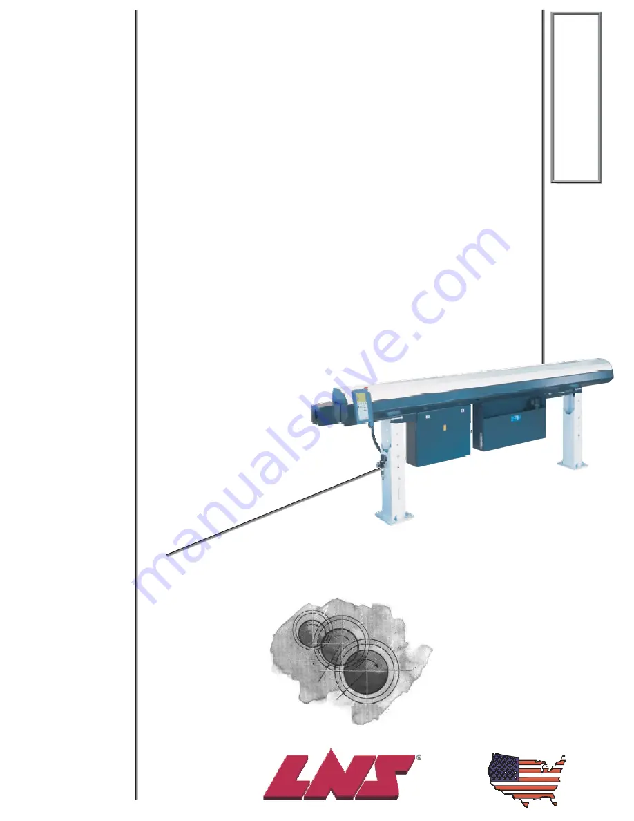
220
220
220
Hydrobar
Express
Hydrobar
Express
Hydrobar
Express
TROUBLESHOOTING
AND
SPARE
PARTS
MANUAL
TROUBLESHOOTING
AND
SPARE
PARTS
MANUAL
TROUBLESHOOTING
AND
SPARE
PARTS
MANUAL
Summary of Contents for Hydrobar Express 220
Page 61: ......
Page 143: ......
Page 147: ......
Page 156: ...Chapter 6 Spare Parts 6 9 HYDROBAR EXPRESS 220 Servo Motor Assembly ...
Page 161: ...6 14 Chapter 6 Spare Parts HYDROBAR EXPRESS 220 Hydraulic Pump Assembly ...
Page 163: ...6 16 Chapter 6 Spare Parts HYDROBAR EXPRESS 220 Diameter Adjustment Motor Assembly ...
Page 164: ...Chapter 6 Spare Parts 6 17 HYDROBAR EXPRESS 220 Air Regulator and Cable Passage Plate ...


