background image

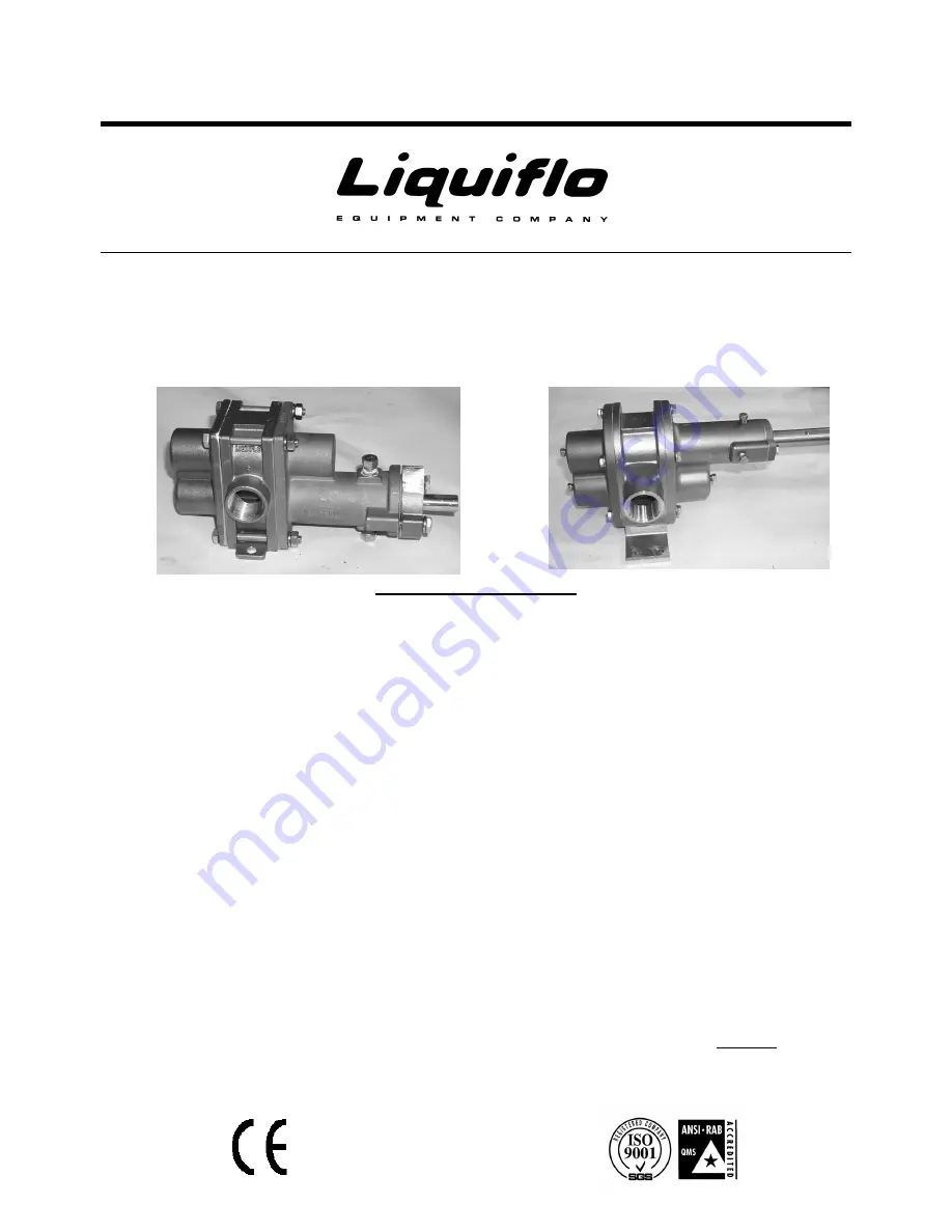
INSTALLATION and MAINTENANCE MANUAL

and H-SERIES

ROTOGEAR

A

SEALED PUMPS

TABLE OF CONTENTS

General Instructions

Symbol Explanation

Pump and Motor Installation

Start Up

Special Precautions for various seals

Removal from System

Maintenance and Repair

Pump Disassembly

Section (A)

Packed stuffing box

Section (B)

Lip Seal

Section (C)

Single internal mechanical seal

Section (D)

External mechanical seal

Section (E)

Double mechanical seal

Trouble Shooting

Document No.: 3.20.073

Liquiflo Equipment Co. 443 North Avenue Garwood, NJ 07027 USA Tel 908-518-0666 Fax 908-518-1847

Summary of Contents for ROTOGEAR 3 Series

Page 1: ...recautions for various seals Removal from System Maintenance and Repair Pump Disassembly Section A Packed stuffing box Section B Lip Seal Section C Single internal mechanical seal Section D External mechanical seal Section E Double mechanical seal Trouble Shooting Document No 3 20 073 Liquiflo Equipment Co 443 North Avenue Garwood NJ 07027 USA Tel 908 518 0666 Fax 908 518 1847 ...

Page 2: ...pplicable to operational safety where risks for health and life of personnel may be posed All cautions should be passed on to other users B Attention Symbol Special attention must be paid in order to maintain a correct operating procedure and to avoid damage to the pump and or other plant equipment INSTALLATION OF PUMP AND MOTOR ASSEMBLY All items included in this section The following should be o...

Page 3: ...37 microns A filter of at least 400 U S Mesh should be installed in the suction line 312 H12 and 314 particle size is 60 microns with a filter mesh of 230 U S Concentration of solids exceeding 1 is not recommended as wear rates will increase to unacceptable levels START UP Insure motor is locked out prior to rotating pump by hand A Turn the pump by hand to insure that it turns freely B Jog the mot...

Page 4: ...e mechanical seal a lubrication loop to pressurize the seal chamber is required The seal chamber should be kept at approximately 5 to 20 psi 3 to 1 4 bar higher than the discharge pressure In addition the flow rate through the seal chamber should be approximately 1 8 GPM for fluids with specific heat values other then 1 0 i e water the flow rate should be adjusted Insure coupling guard is replaced...

Page 5: ...e gland screws 16 lock washers 19 and the gland 17 Note For the 312 H12 and 314 go to step 12 4 A Refer to section A for removal of the packing B Refer to section B for removal of the lip seal C Refer to section C for removal of a single seal D Refer to section D for removal of an external seal E Refer to section E for removal of a double seal 5 Remove the four housing bolts 4 housing nuts 10 and ...

Page 6: ...retaining rings When tightening the center housing bolts use a star pattern torque sequence on the fasteners to insure even compression on the O ring s surface Repeat this process several times waiting between re tightening This is necessary as the Teflon will cold flow Bolt Size Torque in lbs NM 10 32 UNF 28 3 2 1 4 20 UNC 60 6 7 5 16 18 UNC 90 10 312 H12 and 314 Continued from Step 2 Caution The...

Page 7: ...ings three more for the 312 314 and H12 of packing staggering as described above 5 Install split gland and gland screws Do not over tighten the gland screws as the packing should leak at a rate of 8 to 10 drops per minute Section B Lip Seal If the lip seal leaks excessively it needs to be replaced 1 Remove the lip seal 11 from the front housing 2 Install a new lip seal NOTE If the drive shaft exhi...

Page 8: ...eat gaskets or O ring on the seal seat and install into gland 4 Install the mechanical seal face side out with retaining clips still on onto the drive shaft being careful not to damage the seal s wedge Then remove the retaining clips Slide the seal into the seal chamber centering the set screws in the 1 8 inch NPT opening 5 Using gland plate with seat installed press seal into seal chamber until a...

Page 9: ...seat 5 Install gland gland screws and lock washers 6 Install the mechanical seal with retaining clips onto the drive shaft being careful not to damage the seal s wedge Then remove the retaining clips Slide the seal up to the seal seat 7 Compress the mechanical seal by 09 inches 2 3 mm and then tighten the four setscrews Section E Double Mechanical Seal 1 To remove the mechanical seal 11 from the f...

Page 10: ...amber 4 Remove the drive side seal seat 24 and the seal seat gaskets 18 or O rings from the gland 5 Install new seal seat gaskets or O rings on the seal seat and install into gland 6 Install gland gland screws and lock washers Tighten gland screws to 90 in lbs 10 NM 7 Using an Allen Hex Key slide seal retainer metal cartridge to position set screws centrally within the 1 8 inch NPT openings Rotate...

Page 11: ...rn Rebuild pump No Discharge Magnetic coupling broken free Stop pump Wait till there is no rotation restart pump Inlet pressure to low Increase suction pressure Verify suction piping is not to long Fully open any suction valves Clogged strainer Clean strainer Speed to low Increase driver speed if possible A larger size pump may be needed Bypass valve open System pressure higher than relief setting...

Page 12: ...for the correct viscosity Excessive power consumption Differential pressure greater than specified Increase pipe diameter Abrasives in fluid Install suction strainer Corrosion wear Materials of construction not acceptable for fluid being pumped Extended dry running Install power sensor to stop pump Discharge pressure too high Increase pipe diameter Decrease pipe run Rapid pump wear Misalignment Al...

Page 13: ...0 0 15 0 10 0 05 0 1750 1500 1140 900 POWER BHP LPM 2 2 2 0 1 8 1 6 1 4 1 2 1 0 0 8 0 6 0 4 0 2 0 FLOW GPM 600 1750 0 2 4 6 8 BAR 600 DIFFERENTIAL PRESSURE PSI 0 6 0 5 0 4 0 3 0 2 0 1 0 80 60 40 20 100 0 1750 1500 1140 900 POWER BHP 0 2 4 6 8 BAR FLOW GPM 600 1750 LPM 2 2 2 0 1 8 1 6 1 4 1 2 1 0 0 8 0 6 0 4 0 2 0 0 20 0 15 0 10 0 05 0 600 ...

Page 14: ... 4 1 2 1 0 0 8 0 6 0 4 0 2 0 80 60 40 20 100 0 1750 1500 1140 900 POWER BHP FLOW GPM 600 1750 0 4 0 3 0 2 0 1 0 600 LPM 6 5 4 3 2 1 0 0 2 4 6 8 BAR DIFFERENTIAL PRESSURE PSI 80 60 40 20 100 0 1750 1500 1140 900 POWER BHP FLOW GPM 600 1750 600 1 6 1 4 1 2 1 0 0 8 0 6 0 4 0 2 0 LPM 6 5 4 3 2 1 0 0 4 0 3 0 2 0 1 0 ...

Page 15: ... 5 1 0 0 5 0 80 60 40 20 100 0 1750 1500 1140 900 POWER BHP FLOW GPM 1750 600 600 LPM 15 12 9 6 3 0 0 8 0 7 0 6 0 5 0 4 0 3 0 2 0 1 0 0 2 4 6 8 BAR DIFFERENTIAL PRESSURE PSI 80 60 40 20 100 0 1750 1500 1140 900 POWER BHP FLOW GPM 600 1750 600 4 0 3 5 3 0 2 5 2 0 1 5 1 0 0 5 0 LPM 15 12 9 6 3 0 0 8 0 7 0 6 0 5 0 4 0 3 0 2 0 1 0 ...

Page 16: ... 0 0 5 0 80 60 40 20 100 0 1750 1500 1140 900 POWER BHP FLOW GPM 1750 600 600 LPM 11 10 9 8 7 6 5 4 3 2 1 0 0 6 0 5 0 4 0 3 0 2 0 1 0 0 2 4 6 8 BAR DIFFERENTIAL PRESSURE PSI 80 60 40 20 100 0 1750 1500 1140 900 POWER BHP FLOW GPM 600 1750 3 0 2 5 2 0 1 5 1 0 0 5 0 600 LPM 11 10 9 8 7 6 5 4 3 2 1 0 0 6 0 5 0 4 0 3 0 2 0 1 0 ...

Page 17: ... 40 20 100 0 1750 1500 900 POWER BHP FLOW GPM 1750 600 600 1140 1 8 1 6 1 4 1 2 1 0 0 8 0 6 0 4 0 2 0 LPM 45 40 35 30 25 20 15 10 5 0 0 2 4 6 8 BAR DIFFERENTIAL PRESSURE PSI 80 60 40 20 100 0 1750 1500 1140 900 POWER BHP FLOW GPM 600 1750 12 10 8 6 4 2 0 1 8 1 6 1 4 1 2 1 0 0 8 0 6 0 4 0 2 0 600 LPM 45 40 35 30 25 20 15 10 5 0 ...

Page 18: ...0 0 1750 1500 900 POWER BHP FLOW GPM 1750 600 600 1 6 1 4 1 2 1 0 0 8 0 6 0 4 0 2 0 1140 0 2 4 6 8 BAR LPM 36 32 28 24 20 16 12 8 4 0 10 9 8 7 6 5 4 3 2 1 0 DIFFERENTIAL PRESSURE PSI 80 60 40 20 100 0 1750 1500 1140 900 POWER BHP FLOW GPM 600 1750 600 1 6 1 4 1 2 1 0 0 8 0 6 0 4 0 2 0 0 2 4 6 8 BAR LPM 36 32 28 24 20 16 12 8 4 0 ...

Page 19: ...100 0 1750 1500 900 POWER BHP FLOW GPM 1750 600 600 LPM 90 80 70 60 50 40 30 20 10 0 1140 3 5 3 0 2 5 2 0 1 5 1 0 0 5 0 0 2 4 6 8 BAR 25 20 15 10 5 0 DIFFERENTIAL PRESSURE PSI 80 60 40 20 100 0 1750 1500 1140 900 POWER BHP FLOW GPM 600 1750 600 3 5 3 0 2 5 2 0 1 5 1 0 0 5 0 0 2 4 6 8 BAR LPM 90 80 70 60 50 40 30 20 10 0 ...

Page 20: ...14 12 10 8 6 4 2 0 80 60 40 20 100 0 1750 1500 900 POWER BHP FLOW GPM 1750 600 600 LPM 60 50 40 30 20 10 0 1140 2 5 2 0 1 5 1 0 0 5 0 0 2 4 6 8 BAR 16 14 12 10 8 6 4 2 0 DIFFERENTIAL PRESSURE PSI 80 60 40 20 100 0 1750 1500 1140 900 POWER BHP FLOW GPM 600 1750 600 2 5 2 0 1 5 1 0 0 5 0 LPM 60 50 40 30 20 10 0 ...

Page 21: ...0 100 0 900 POWER BHP FLOW GPM 1140 600 300 1140 LPM 120 100 80 60 40 20 0 300 0 2 4 6 8 BAR 5 0 4 5 4 0 3 5 3 0 2 5 2 0 1 5 1 0 0 5 0 0 2 4 6 8 BAR DIFFERENTIAL PRESSURE PSI 80 60 40 20 100 0 600 POWER BHP FLOW GPM 300 1140 35 30 25 20 15 10 5 0 300 5 0 4 5 4 0 3 5 3 0 2 5 2 0 1 5 1 0 0 5 0 900 LPM 120 100 80 60 40 20 0 1140 ...

Page 22: ...0 0 1140 600 POWER BHP FLOW GPM 300 1140 FLOW LPM 300 90 80 70 60 50 40 30 20 10 0 4 0 3 5 3 0 2 5 2 0 1 5 1 0 0 5 0 900 0 2 4 6 8 BAR DIFFERENTIAL PRESSURE PSI 25 20 15 10 5 0 80 60 40 20 100 0 900 POWER BHP FLOW GPM 1140 600 300 FLOW LPM 90 80 70 60 50 40 30 20 10 0 1140 4 0 3 5 3 0 2 5 2 0 1 5 1 0 0 5 0 300 0 2 4 6 8 BAR ...

Page 23: ...PSI 80 60 40 20 100 0 900 POWER BHP FLOW GPM 1140 600 300 1140 LPM 250 200 150 100 50 0 300 9 8 7 6 5 4 3 2 1 0 70 60 50 40 30 20 10 0 DIFFERENTIAL PRESSURE PSI 80 60 40 20 100 0 600 POWER BHP FLOW GPM 1140 300 70 60 50 40 30 20 10 0 1140 900 300 9 8 7 6 5 4 3 2 1 0 0 2 4 6 8 BAR LPM 250 200 150 100 50 0 ...

Reviews: