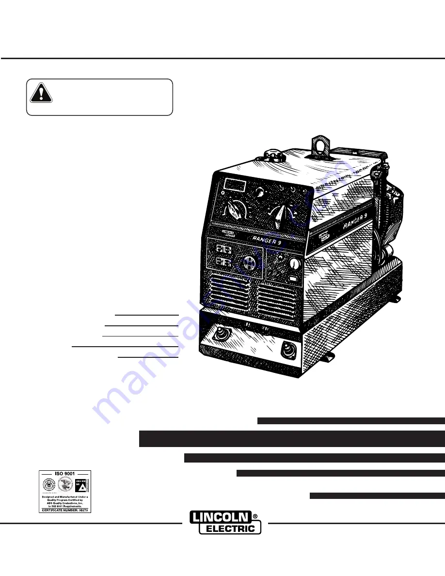
background image

RANGER       9

Multi-Process Gasoline Engine Driven Welder and Power Generator

OPERATOR’S MANUAL

IM753-A

January, 2003

Safety Depends on You

Lincoln arc welding and cutting
equipment is designed and built
with safety in mind. However, your
overall safety can be increased by
proper installation ... and thought-
ful operation on your part.

DO

NOT INSTALL, OPERATE OR
REPAIR THIS EQUIPMENT
WITHOUT READING THIS
MANUAL AND THE SAFETY
PRECAUTIONS CONTAINED
THROUGHOUT.

And, most

importantly, think before you act
and be careful.

For use with machines having Code Numbers:

10909, 10939

• Sales and Service through Subsidiaries and Distributors Worldwide •

Cleveland, Ohio 44117-1199  U.S.A.   TEL: 216.481.8100   FAX: 216.486.1751   WEB SITE: www.lincolnelectric.com

• World's Leader in Welding and Cutting Products •

Date of Purchase:
Serial Number:
Code Number:
Model:
Where Purchased:

Copyright © 2003 Lincoln Global Inc.

This manual covers equipment which is no 
longer in production by The Lincoln Electric Co.  
Specifications and availability of optional 
features may have changed.

Summary of Contents for RANGER 9 IM753-A

Page 1: ...Y PRECAUTIONS CONTAINED THROUGHOUT And most importantly think before you act and be careful For use with machines having Code Numbers 10909 10939 Sales and Service through Subsidiaries and Distributors Worldwide Cleveland Ohio 44117 1199 U S A TEL 216 481 8100 FAX 216 486 1751 WEB SITE www lincolnelectric com World s Leader in Welding and Cutting Products Date of Purchase Serial Number Code Number...

Page 2: ...R WEARERS SHOULD CONSULT WITH THEIR DOCTOR BEFORE OPERATING Read and understand the following safety highlights For additional safety information it is strongly recommended that you purchase a copy of Safety in Welding Cutting ANSI Standard Z49 1 from the American Welding Society P O Box 351040 Miami Florida 33135 or CSA Standard W117 2 1974 A Free copy of Arc Welding Safety booklet E205 is availa...

Page 3: ...ical earth ground 3 f Maintain the electrode holder work clamp welding cable and welding machine in good safe operating condition Replace damaged insulation 3 g Never dip the electrode in water for cooling 3 h Never simultaneously touch electrically hot parts of electrode holders connected to two welders because voltage between the two can be the total of the open circuit voltage of both welders 3...

Page 4: ...event the welding sparks from starting a fire Remember that welding sparks and hot materials from welding can easily go through small cracks and openings to adjacent areas Avoid welding near hydraulic lines Have a fire extinguisher readily available 6 b Where compressed gases are to be used at the job site special precautions should be used to prevent hazardous situations Refer to Safety in Weldin...

Page 5: ...propriés et non inflammables 4 Des gouttes de laitier en fusion sont émises de l arc de soudage Se protéger avec des vêtements de protection libres de l huile tels que les gants en cuir chemise épaisse pan talons sans revers et chaussures montantes 5 Toujours porter des lunettes de sécurité dans la zone de soudage Utiliser des lunettes avec écrans lateraux dans les zones où l on pique le laitier 6...

Page 6: ...he information must be followed to avoid minor personal injury or damage to this equipment CAUTION Please Examine Carton and Equipment For Damage Immediately When this equipment is shipped title passes to the purchaser upon receipt by the carrier Consequently Claims for material damaged in shipment must be made by the purchaser against the transportation company at the time the shipment is receive...

Page 7: ... Power Connections A 8 Premises Wiring A 9 Operation Section B Safety Precautions B 1 General Description B 1 Recommended Applications B 2 Auxiliary Power B 2 Welder Operation B 2 Fuel Consumption B 3 Welder Controls Functions and Operations B 3 Idler Switch B 4 Welding B 4 Auxiliary Power B 4 Starting Shutdown Instructions B 4 Onan Engine B 4 Kohler Engine B 4 Stoping the Engine B 4 Break In Peri...

Page 8: ... D 3 Engine Maintenance Parts D 3 ________________________________________________________________________ Troubleshooting Section E Safety Precautions E 1 How to Use Troubleshooting Guide E 1 Troubleshooting Guide E 2 thru E 5 ________________________________________________________________________ Wiring Diagrams Dimension Print Section F _________________________________________________________...

Page 9: ...with Cast Ranger 9 Iron Liners Fuel 9 gal 34L Kohler Electronic 20 HP Low Idle 38 1 cu in Lubricating Oil Command Ignition 2200RPM 624 cc in 2 0 Qts 1 9L CH20S INPUT GASOLINE ENGINE RATED DC OUTPUT WELDER MODEL HEIGHT WIDTH DEPTH WEIGHT Ranger 9 Onan 30 3 in 770 mm 19 2 in 488 mm 42 3 in 1075 mm 598 lbs 272 kg P220 OHV Ranger 9 Kohler 591 lbs 269 kg Command CH20S MACHINE OUTPUT GENERATOR Welding O...

Page 10: ...0 60 70 80 DC STICK TIG CC OUTPUT OUTPUT AMPS OUTPUT VOLTS DC RMS A 210 OUTPUT RANGE B 50 OUTPUT RANGE A B 0 50 100 150 200 250 300 350 0 10 20 30 40 50 60 70 80 55 50 45 40 35 30 25 20 15 10 5 0 0 50 100 150 200 250 300 350 400 OUTPUT AMPS OUTPUT VOLTS DC HIGH MED LOW SPECIFICATIONS 0 50 100 150 200 250 300 350 400 450 0 50 100 150 200 250 300 350 250 250 45 45 ...

Page 11: ...ions where unarrested sparks may present a fire hazard The standard muffler included with this welder does not qualify as a spark arrester When required by local regulations the K894 1 spark arrester must be installed and properly maintained An incorrect arrester may lead to damage to the engine or adversely affect performance UNDERCARRIAGES The recommended trailer for use with this equipment for ...

Page 12: ...uds provided These connections should be checked periodically and tightened if neces sary Loose connections will result in overheating of the output studs When welding at a considerable distance from the welder be sure you use ample size welding cables Listed below are copper cable sizes recommended for the rated current and duty cycle Lengths stipulated are the distance from the welder to work an...

Page 13: ...st coming out on the left side The exhaust can be changed to the opposite side by removing the two screws that hold the exhaust port cover in place and installing the cover on the opposite side Operating the Ranger 9 without the cover in place will result in a higher noise level and no increase in machine output CONNECTION OF LINCOLN ELECTRIC WIRE FEEDERS Shut off welder before making any electric...

Page 14: ...eing used Set the RANGE switch to either HIGH MED or LOW as required by the process Set the WELDING TERMINAL Control switch to the ALWAYS ON position Set the IDLER switch to the AUTO position Connection of the Magnum Spool Gun and SG Control Module to the Ranger 9 Shut off the welder Connect per the instructions on the appropriate con nection diagram in the rear of this manual Set the output contr...

Page 15: ...rrent rating of any plug used with the system must be at least equal to the current load through the associated receptacle Refer to Tables l and ll Do not attempt to connect power receptacles in parallel MOTOR STARTING Most 1 5 hp AC single phase motors can be started if there is no load on the motor or other load connected to the machine since the full load current rating of a 1 5 hp motor is app...

Page 16: ... operated with the idler switch in the HIGH idle position to avoid load sensing problems If the machine is set for automatic idle the 230 volt circuit will sense loads and cause the engine to accelerate to high idle However since only one line of the circuit senses current 115 volt power drawn from only one line to neutral may result in the engine not going to high idle WARNING Install a double po...

Page 17: ...ocal requirements A double pole double throw transfer switch in conjunction with the properly rated double throw circuit breaker is connected between the generator power and the utility meter WARNING 230 Volt 60 Hz 3 Wire Service POWER COMPANY METER 230 VOLT 115 VOLT 115 VOLT LOAD N NEUTRAL BUS GROUND PREMISES DISCONNECT AND SERVICE OVERCURRENT PROTECTION GND N NOTE No 8 COPPER CONDUCTOR CABLE SEE...

Page 18: ...nd body protection ENGINE EXHAUST can kill Use in open well ventilated areas or vent exhaust to the outside Do not stack anything on or near the engine MOVING PARTS can injure Do not operate this equipment with any of its doors open or guards off Stop the engine before servicing it Keep away from moving parts Only qualified personnel should install use or ser vice this equipment Additional Safety ...

Page 19: ...N 25 includes gas solenoid LN 25 K449 Includes internal contactor for across the arc operation no control cable Provides cold electrode until gun trigger is pressed Includes gas solenoid K444 1 Remote Voltage Control Kit is required for voltage control at the feeder LN 742 K617 1 or K618 1 or LN 742H K617 2 or K618 2 requires K619 xx Input Cable Assembly Provides cold electrode until gun trigger i...

Page 20: ...ns are made at the 6 pin or 14 pin amphenol connector For remote control the toggle switch is set in the REMOTE CONTROL position For control at the welder control panel the toggle switch is set in the CONTROL AT WELDER position WELDING TERMINALS SWITCH The Toggle switch labeled WELDING TERMINALS ALWAYS ON and WELDING TERMINALS REMOTELY CONTROLLED is used to control the operation of the welder outp...

Page 21: ... oil change The oil filter is to be changed at the second oil change Refer to the Engine Owner s Manual for more informa tion Kohler CH20S 5 HRS Onan P220 OHV 20 HRS B 4 OPERATION B 4 RANGER 9 With the switch in the REMOTELY CONTROLLED position the contactor is open at LOW idle and HIGH idle until a control cable is attached to the welder amphenol connector from a wire feeder Under this condition ...

Page 22: ...he TIG Module is to be set for CONTINU OUS HF The following settings and electrodes are recommended When AC TIG welding the actual maximum welding current is 40 to 80 amps higher than the current marked on the RANGE SWITCH dial This is a result of a lower effective reactance due to the natural rectifi cation that occurs with the AC TIG welding process WIRE FEED Constant Voltage Welding The Ranger ...

Page 23: ...gger LN 25 with 42V RANGER 9 contactor Remote Control Kit closes Welding starts immediately and engine goes to high idle Wire Feed CV No Auto At Welder Always on Cold Press gun trigger LN25 LN 25 with internal contactor closes Weld contactor ing starts immediately and engine goes to high idle Wire Feed CV Yes Auto Remote Remote Cold Press gun trigger LN 742 RANGER 9 contactor closes Welding starts...

Page 24: ...KVA plug rated at 115 230V 50 amps K1690 1 GFCI RECEPTACLE KIT Includes one UL approved 120V ground fault circuit interrupter duplex type receptacle with cover and installation instructions Replaces the factory installed 120V duplex receptacle Each receptacle of the GFCI Duplex is rated at 20 Amps the maximum total current from the GFCI Duplex is limit ed to the 20 Amps Two kits are required K704 ...

Page 25: ... or an authorized Field Service Shop D 1 MAINTENANCE D 1 ROUTINE MAINTENANCE At the end of each day s use refill the fuel tank to minimize moisture condensation in the tank Running out of fuel tends to draw dirt into the fuel system Also check the crankcase oil level and add oil if indicated OIL Maintenance schedule for changing the oil and oil filter after break in The above schedule is for norma...

Page 26: ...ter mounting base then use an oil fil ter socket tool to tighten the filter an additional 1 2 to 7 8 turn Refill the crankcase with the specified amount of the recommended oil Reinstall the oil filler cap Start the engine and check for oil filter leaks Stop the engine and check the oil level If neces sary add oil to the upper limit mark on RANGER 9 SLIP RINGS A slight amount of darkening and wear ...

Page 27: ...lamp When reistalling connect negative cable last Keep well ventilated USING A BOOSTER connect positive lead to battery first then connect negative lead to engine foot BATTERY ACID CAN BURN EYES and SKIN Wear gloves and eye protection and be careful when working near battery Follow instructions printed on battery WARNING BATTERY When replacing jumping or otherwise connecting the battery to the bat...

Page 28: ... CAUSE lists the obvious external possibilities that may contribute to the machine symptom Step 3 RECOMMENDED COURSE OF ACTION This column provides a course of action for the Possible Cause generally it states to contact your local Lincoln Authorized Field Service Facility If you do not understand or are unable to perform the Recommended Course of Action safely contact your local Lincoln Authorize...

Page 29: ... ACTION If all recommended possible areas of misadjustment have been checked and the problem persists Contact your local Lincoln Authorized Field Service Facility 1 Open in miscellaneous leads 2 Open lead in flashing or field circuit 3 Faulty rotor 4 Faulty Potentiometer R1 5 Faulty stator Field winding 6 Faulty Field rectifier D2 7 Faulty P C Board 1 Idler switch on High Idle 2 Insufficient volta...

Page 30: ...r terminal block connection faulty 6 Faulty P C Board Onan engine 1 Fuel filter clogged 2 Air filter clogged 1 Spark plugs do not have specified gap 2 Spark plugs are fouled E 3 TROUBLESHOOTING E 3 RANGER 9 Observe all Safety Guidelines detailed throughout this manual If for any reason you do not understand the test procedures or are unable to perform the tests repairs safely contact your Local Li...

Page 31: ...unctioning Wire feeder does not work when connected to welder amphenol 1 Faulty battery 2 Faulty charging system 3 Loose or broken lead in charging circuit 1 Output control switch in wrong position 2 Output control switch defective 3 Output control potentiometer defective 4 Faulty wiring 5 Faulty P C Board 1 Output control switch in wrong position 2 Remote control leads broken in control cable 3 F...

Page 32: ...ntactor 5 Faulty P C Board PCB1 1 WELDING TERMINALS switch in wrong position 2 Faulty wiring in contactor circuit 3 Faulty amphenol or bypass P C Board PCB2 4 Faulty contactor 5 Faulty P C Board PCB1 6 Faulty control cable from wire feeder or amphenol 7 Faulty wire feeder 1 Faulty wiring 2 Faulty amphenol or bypass P C Board PCB2 3 Faulty contactor 4 Faulty P C Board PCB1 If all recommended possib...

Page 33: ...EW BLOWER BAFFLE OUTPUT RHEOSTAT OIL PRESSURE SWITCH FLYWHEEL ALTERNATOR ENGINE FOOT ENGINE CROSS SUPPORT GND H B WELDING TERMINAL CONTROL SWITCH 25 OHM 240 GND E 242 GND E VOLTAGE IGNITION MODULE DIAGRAM A ENGINE TERMINAL BLOCK CONNECTION SEE DIAGRAM A FOR ENGINE TERMINAL BLOCK CONNECTION S2A CLOSED WITH S2 IN C1 C2 OR C3 POSITION RANGE SWITCH S2 10AMP 200A 200 201 ROTOR FIELD C1 800 MFD D2 AC AC...

Page 34: ...h electrically live parts Keep guards in place Keep away from moving parts Only qualified personnel should install use or service this equipment N A WELDING CABLE MUST BE SIZED FOR CURRENT AND DUTY CYCLE OF APPLICATION N D INSULATE EACH UNUSED LEAD INDIVIDUALLY N E SPLICE LEADS AND INSULATE N B USE POLARITY SWITCH TO SET FOR DESIRED ELECTRODE POLARITY POSITION THE OUTPUT SELECTOR SWITCH TO A CV PO...

Page 35: ...CONNECTION N D FOR WIRE FEEDERS THAT RETURN A SIGNAL FOR WELDING OUTPUT USE ISOLATION RELAY TO CLOSE LEADS 2 4 K867 UNIVERSAL ADAPTER PLUG 14 PIN AMPHENOL TO WORK ELECTRODE TO WORK N E REFER TO POWER SOURCE INSTRUCTION MANUAL FOR MAXIMUM AUXILIARY CURRENT DRAW CAUTION N B USE POLARITY SWITCH TO SET DESIRED POLARITY POSITION THE OUTPUT SELECTOR SWITCH TO A CV POSITION WARNING Do not operate with pa...

Page 36: ...T ADJUST ABOVE RPM SPECIFICATIONS LISTED IN THE ENGINE WELDER OPERATING MANUAL N B WELDING CABLES MUST BE OF PROPER CAPACITY FOR THE CURRENT AND DUTY CYCLE OF IMMEDIATE AND FUTURE APPLICATIONS SEE OPERATING MANUAL K592 CONTROL CABLE N A USE POLARITY SWITCH TO SET FOR DESIRED ELECTRODE POLARITY POSITION THE OUTPUT SELECTOR SWITCH TO A CV POSITION N C IF OPTIONAL REMOTE OUTPUT CONTROL IS USED PLACE ...

Page 37: ...AN INCREASE IN THE THE AC AUXILIARY VOLTAGE IF THIS VOLTAGE GOES OVER 140 VOLTS WIRE FEEDER CONTROL CIRCUITS MAY BE PLACE WELDER TERMINALS SWITCH TO REMOTELY CONTROLLED POSITION N D PLACE IDLER SWITCH IN AUTO OR HIGH IDLE POSITION AS DESIRED RANGER 9 LN 25 WITH 42 VOLT REMOTE OUTPUT CONTROL MODULE CONNECTION DIAGRAM K626 XX INPUT CABLE ASSEMBLY TO LN 25 INPUT CABLE PLUG 4 19 96D S20909 can kill EL...

Page 38: ...G IS PRE SET AT THE FACTORY DO NOT ADJUST ABOVE RPM SPECIFICATIONS LISTED IN THE ENGINE WELDER OPERATING MANUAL AN INCREASE IN THE THE AC AUXILIARY VOLTAGE IF THIS VOLTAGE GOES OVER 140 VOLTS WIRE FEEDER CONTROL CIRCUITS MAY BE PLACE WELDING TERMINALS SWITCH TO REMOTELY CONTROLLED POSITION N D PLACE IDLER SWITCH IN HIGH IDLE POSITION RANGER 14 PIN WIRE FEEDER RECEPTACLE K488 SG CONTROL MODULE BE S...

Page 39: ...9 CENTER OF GRAVITY WITH OIL IN ENGINE AND EMPTY FUEL TANK 20 51 30 28 9 29 9 31 30 00 UNDERCARRIAGE MOUNTING HOLES L 9 09 26 59 2 75 17 00 C OF SHAFT FOR OIL FILTER REMOVAL NOT REQUIRED WITH KOHLER ENGINE 42 00 30 00 20 63 25 25 DIMENSION PRINT RANGER 9 ...

Page 40: ...NOTES RANGER 9 ...

Page 41: ...NOTES RANGER 9 ...

Page 42: ...electrically live parts or electrode with skin or wet clothing Insulate yourself from work and ground No toque las partes o los electrodos bajo carga con la piel o ropa moja da Aislese del trabajo y de la tierra Ne laissez ni la peau ni des vête ments mouillés entrer en contact avec des pièces sous tension Isolez vous du travail et de la terre Berühren Sie keine stromführenden Teile oder Elektrode...

Page 43: ...gute Be und Entlüftung des Arbeitsplatzes Mantenha seu rosto da fumaça Use ventilação e exhaustão para remover fumo da zona respiratória Turn power off before servicing Desconectar el cable de ali mentación de poder de la máquina antes de iniciar cualquier servicio Débranchez le courant avant l entre tien Strom vor Wartungsarbeiten abschalten Netzstrom völlig öff nen Maschine anhalten Não opere co...

Page 44: ...s and Service through Subsidiaries and Distributors Worldwide Cleveland Ohio 44117 1199 U S A TEL 216 481 8100 FAX 216 486 1751 WEB SITE www lincolnelectric com World s Leader in Welding and Cutting Products ...

Reviews: