Light Sky IPL6103, User Manual
The user manual for the Light Sky IPL6103 is available for free download on our website. This comprehensive manual provides detailed instructions and guidelines on how to effectively operate and maintain your Light Sky IPL6103 product. Get your free user manual today from manualshive.com and make the most of your IPL6103 experience.
Share
Download


Reviews:
No comments
Related manuals for IPL6103

PT-RZ470EAW
Brand: Panasonic Pages: 138

EP21713
Brand: Costway Pages: 28

EH501
Brand: Optoma Pages: 93

Fujicascope M3
Brand: FujiFilm Pages: 20

L3403FHD
Brand: i3-TECHNOLOGIES Pages: 76

EVO160F
Brand: ProLights Pages: 44

WTH 4765
Brand: Wize Pages: 2

Z3472031K
Brand: Barco Pages: 14

CP-14t
Brand: BOXLIGHT Pages: 40

LumiPlus Wireless PAR56
Brand: Astrapool Pages: 24

PB63U
Brand: LG Pages: 69

RL-JA20
Brand: LG Pages: 68

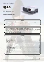
RD-JT91
Brand: LG Pages: 34

PF80G
Brand: LG Pages: 72
AJ-LBX3A
Brand: LG Pages: 8

PF80A
Brand: LG Pages: 78

AJ-LCF3
Brand: LG Pages: 4
RD-JT40 1024X768 XGA
Brand: LG Pages: 90


