Summary of Contents for RU-48SZ40
Page 20: ...Block Diagram 20 ...
Page 21: ... 21 ...
Page 22: ... 22 ...
Page 23: ... 23 ...
Page 35: ......
Page 36: ......
Page 37: ......
Page 38: ......
Page 39: ......
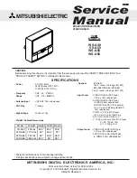
The LG RU-48SZ40, a high-quality television, comes with a downloadable Service Manual. This comprehensive manual offers detailed instructions and troubleshooting solutions to enhance your TV experience. Users can conveniently download this manual for free from our website, ensuring smooth operation and maximum enjoyment of the product.
Page 20: ...Block Diagram 20 ...
Page 21: ... 21 ...
Page 22: ... 22 ...
Page 23: ... 23 ...
Page 35: ......
Page 36: ......
Page 37: ......
Page 38: ......
Page 39: ......