Lewmar AutoAnchor 560 V2, Owner'S Manual
The Lewmar AutoAnchor 560 V2 is a cutting-edge anchor system that ensures hassle-free anchoring on your boat. To get the most out of this high-quality product, make sure to download the free Owner's Manual from our website manualshive.com. This comprehensive manual is a must-have for users looking to maximize their sailing experience.
Share
Download


Reviews:
No comments
Related manuals for AutoAnchor 560 V2

FC-8030
Brand: UNISource Corporation Pages: 22

SurePOS 514
Brand: IBM Pages: 162

TE-2000
Brand: Casio Pages: 3

SE-S100
Brand: Casio Pages: 91

EnergyCam Open Wire
Brand: Fast Forward Pages: 2

AB4200
Brand: AccuBANKER Pages: 18

SI-13-485
Brand: Vega Pages: 31

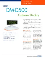
DM-D500 Series
Brand: Epson Pages: 42
DM-D500 Series
Brand: Epson Pages: 2

DM-D500 Series
Brand: Epson Pages: 82

CMS 218T
Brand: OfficeMaster Pages: 3

EMEC-12
Brand: Hotraco agri Pages: 5

NCH058
Brand: Compact pro Pages: 6

BC-1046D
Brand: MULTISPAN Pages: 4

53210A
Brand: Agilent Technologies Pages: 44


